2.1. Software Architecture
The EE-UQ app is one of SimCenter’s computational applications, which are scientific workflow systems that execute a sequence of computational tasks specialized for natural hazard engineering (NHE) problems. In contrast to more general-purpose scientific workflow systems (such as Taverna, Kepler, and Pegasus), SimCenter workflow systems include the following features:
Access to high-performance computing resources, available on the cloud through DesignSafe, to enable parallel workflows for large-scale NHE problems;
Uncertainty quantification capabilities using Dakota, which allow users to introduce input uncertainties that are propagated through the workflow with random variables;
Streamlined interfaces between existing software applications and datasets widely used by the NHE community, such as OpenFOAM, OpenSees, ADCIRC, and PEER Strong Ground Motion Databases. To do this, the SimCenter develops pre- and post-processors for these existing applications and utilizes web technologies for accessing online services;
Additional custom software applications produced by the SimCenter. Among these are applications that automate the acquisition of building inventory data (BRAILS), applications that simulate hazard events and generate corresponding input files for passing through the workflow system (RegionalEvent Applications), applications for damage and loss assessment (pelicun), and more;
A modular framework that allows developers to incorporate their own software applications as components to the workflow system, as long as they meet the input-output structure at component interfaces.
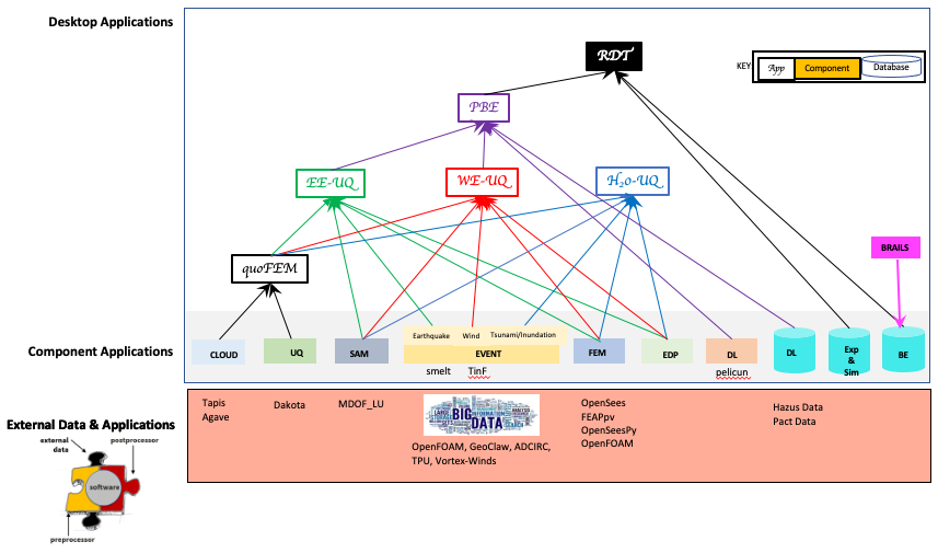
Fig. 2.1.2 SimCenter Software Framework
A Level 1 diagram showing the system context for the SimCenter applications, i.e., how it fits in the world, is shown in Fig. 2.1.3. It shows SimCenter applications (EE-UQ, WE-UQ, HydroUQ, PBE, R2D) as a box in the center surrounded by the user and the user’s systems. The SimCenter applications allow a user to create and run scientific workflow applications; the data for the applications may be obtained from the web or DataDepot. The workflow applications are run on either the local desktop or on an HPC at DesignSafe.
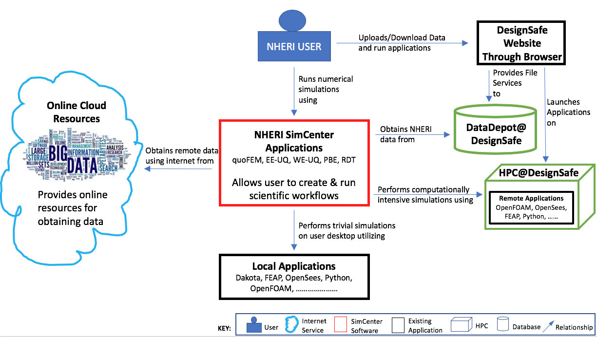
Fig. 2.1.3 System context diagram for SimCenter applications.
Given how SimCenter applications fit in with the environment, a Level 2 diagram demonstrates how the SimCenter applications are broken into high-level components. The SimCenter applications are, as shown in Fig. 2.1.4, split into two components: a front-end UI and a back-end application that runs the workflow. The front-end applications are desktop applications written using the cross-platform Qt framework. The back end is an application that processes the input from the front end, which comes in the form of a JSON file, creates a workflow, and runs it. The workflow applications, written in Python, C, or C++, utilize existing applications where possible and run on either the local desktop machine or on an HPC using resources made available to the NHE community through DesignSafe.
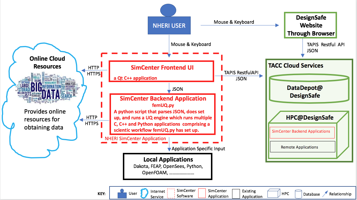
Fig. 2.1.4 System container diagram for SimCenter applications.
Two Level 3 diagrams are now presented, which break up the two containers into the major building blocks or components in C4 terminology. In Fig. 2.1.5, the component diagram for the front-end UI is presented. It outlines the interaction between the user and the individual graphical elements (widgets) of the UI. Given the jigsaw puzzle analogy, the user selects which piece of the jigsaw puzzle they are working on in the component selection widget. The widget for the jigsaw piece will then be displayed on the desktop. The user for each jigsaw piece then selects which application to run for that piece. For the chosen application, they provide the inputs. When the inputs are all provided, the user can choose to run the simulations locally or remotely. For jobs that run remotely, the user can download and review previously run simulations. As seen, the widgets may subsequently interact with web services through HTTPS requests or with DesignSafe utilizing TAPIS Restful API through the RemoteService container.
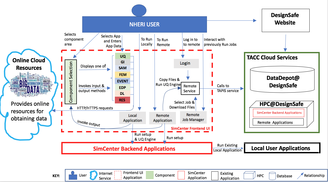
Fig. 2.1.5 Component diagram for front-end UI.
The component diagram for the back-end application shown in Fig. 2.1.6, shows that the back-end comprises several component applications. The application femUQ.py is the application that parses the input from the front end, sets up the workflow by creating a workflow_driver script, and then launches the UQ engine. The choice of UQ engine and applications to run in the workflow is determined from the data passed from the UI and information contained in a file, WorkflowApplication.json. The WorkflowApplication.json file is a file that maps the applications specified in the output from the UI with a specific application contained on the user’s local machine or at the remote HPC resource. As such, it allows the researchers to modify the applications that may be run in the workflow without the need to recompile the application. Once the workflow_driver file is created, control is passed to a UQ engine, which repeatedly runs the workflow_driver to generate the results. In running the workflow, some of the applications will invoke applications not developed to meet the API. For such applications, pre- and post-processors are provided. The figure shows the back-end application running locally or remotely on an HPC at DesignSafe.
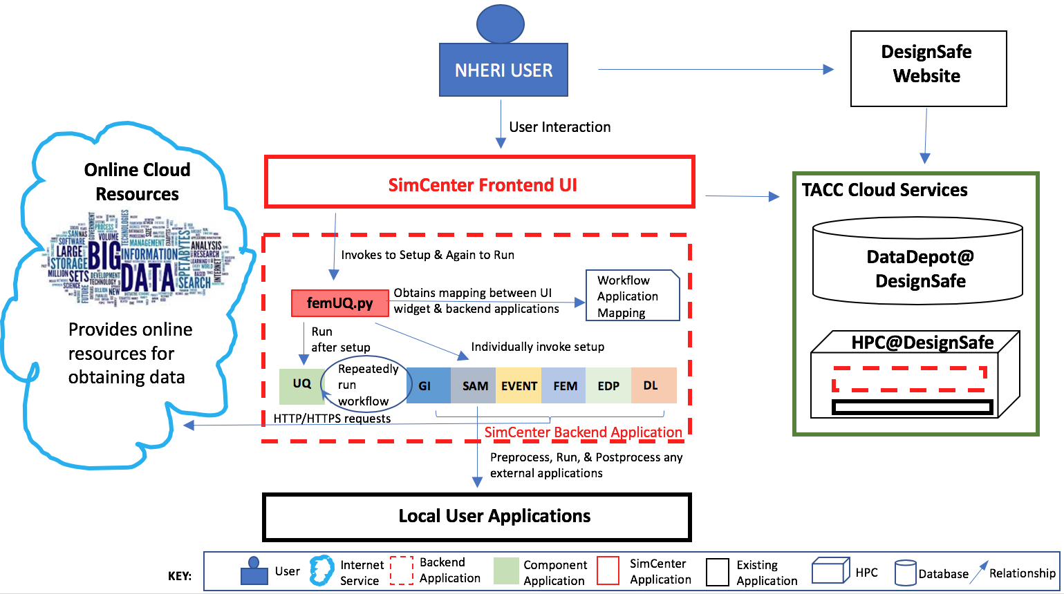
Fig. 2.1.6 Component diagram for back-end application.
Note
femUQ.py is the back-end application for the EE-UQ, WE-UQ, Hydro-UQ, and PBE applications. For R2D, the back-end application is R2D_Workflow.py.
The interaction between the front-end and the back-end is best understood by looking at the sequence of events when the user presses the Run button. As shown in the figure below, the UI application will first perform several steps:
It will create a temporary directory in the Documents folder named
tmp.SimCenter, and insidetmp.SimCenterit will create another directorytemplatedir.It will then run through all the currently selected widgets and invoke the
copyFiles()method, telling these widgets to copy all files needed during the workflow to thetemplatedirdirectory.It will then create a JSON file and will run through the currently selected widgets and invoke the methods
outputToJSON()andoutputAppDataToJSON(), telling the application to augment the JSON file with the inputs the user has provided in the widget and also the name of the widget.The UI will start the back-end application and spin until the back-end application returns with a completion signal.
Now that the UI has handed over to the back-end application, the back-end application will perform the following steps:
Open the output file from the UI and parse it to obtain the name of the application to run and the arguments to run the application with. Open another file, the
WorkflowApplications.jsonfile, contained within the application to determine, given the application name, the full path to the executable to be invoked. It will create intemplatedira file namedworkflow_driver. When run by the UQ engine, this file is a script file that will generate a file namedresults.out.results.outwhen theworkflow_driverscript has completed will contain a single line of space-separated values, one value for each EDP.It will invoke each application with supplied arguments and an additional command-line argument,
--getRV, to inform the application to process the input file and create any additional random variables and input files needed before the workflow runs.It will then launch the UQ engine. The UQ engine is typically a pre- and post-processor to an existing UQ engine.
The pre-processor takes the JSON input file and creates an input file needed by the actual UQ engine.
The pre-processor will launch the UQ application. This application will typically run the
workflow_drivermany times, passing as input to the workflow a file\paramsand obtaining output from theworkflow_drivera fileresults.out.When done, the engine will output its results.
The UQ engine will notify the UQ pre-processor that it is done.
The UQ pre-processor will notify the femUQ application that it is done.
The femUQ application will notify the UI that it is done.
The UI will read the results and present them to the user.
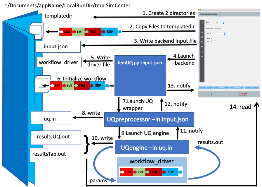
Fig. 2.1.7 Sequence diagram showing what happens when a workflow runs locally.
That is for the case where the computations are performed on the local computer. When the computations are performed remotely, the steps are different. The first eight steps are the same. But now, the UQ wrapper will not start the UQ engine. Instead, control is returned to the UI. The UI will, as shown in the following: (11) Compress the temporary folder, (12) Send the compressed folder to the remote HPC, shown in Fig. 2.1.8, (13) Start an application to perform the computations. All the remote data transfer and application invocation is done through a cloud service. The TACC Tapis interface is used to provide SimCenter users with access to the TACC HPC resources through the DesignSafe portal.
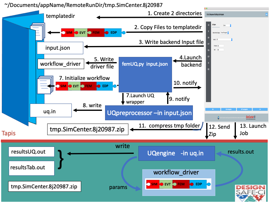
Fig. 2.1.8 Sequence diagram showing what happens when a workflow runs remotely.