2.3. SIM: Structural Model
The user here defines the structural system of the building. The structural system is the part of the building provided to resist the gravity loads and those loads arising from the natural hazard. Several backend applications are provided for this part of the workflow, each responsible for defining the structural analysis model. The user can select the application to use from the drop-down menu at the top of this panel. As the user switches between applications, the input panel changes to reflect the inputs each particular application requires. At present, there are two backend applications available.
2.3.1. Multiple Degrees of Freedom (MDOF)
This panel is provided for users to quickly create simple shear models of a building. The panel, as shown in Fig. 2.3.1.1 is divided into 3 frames:
The top left frame allows the user to specify the number of stories and properties that are constant for every floor and story in the building. The following properties are available: floor weight, story height, torsional stiffness, initial stiffness, yield strength, and hardening ratio for each direction in each story. The user has the option of specifying values for eccentricity of mass in \(x\) and \(y\) directions, and eccentricities for the location of the response quantities. Here, the one and two directions are orthogonal \(x\) and \(y\) axes in plan view.
The lower left frame allows the user to override the structural parameters above for individual floors and stories.
The frame on the right is a graphical widget showing the current building. When entering data into the lower-left frame, the stories corresponding to the modified data are highlighted in red.
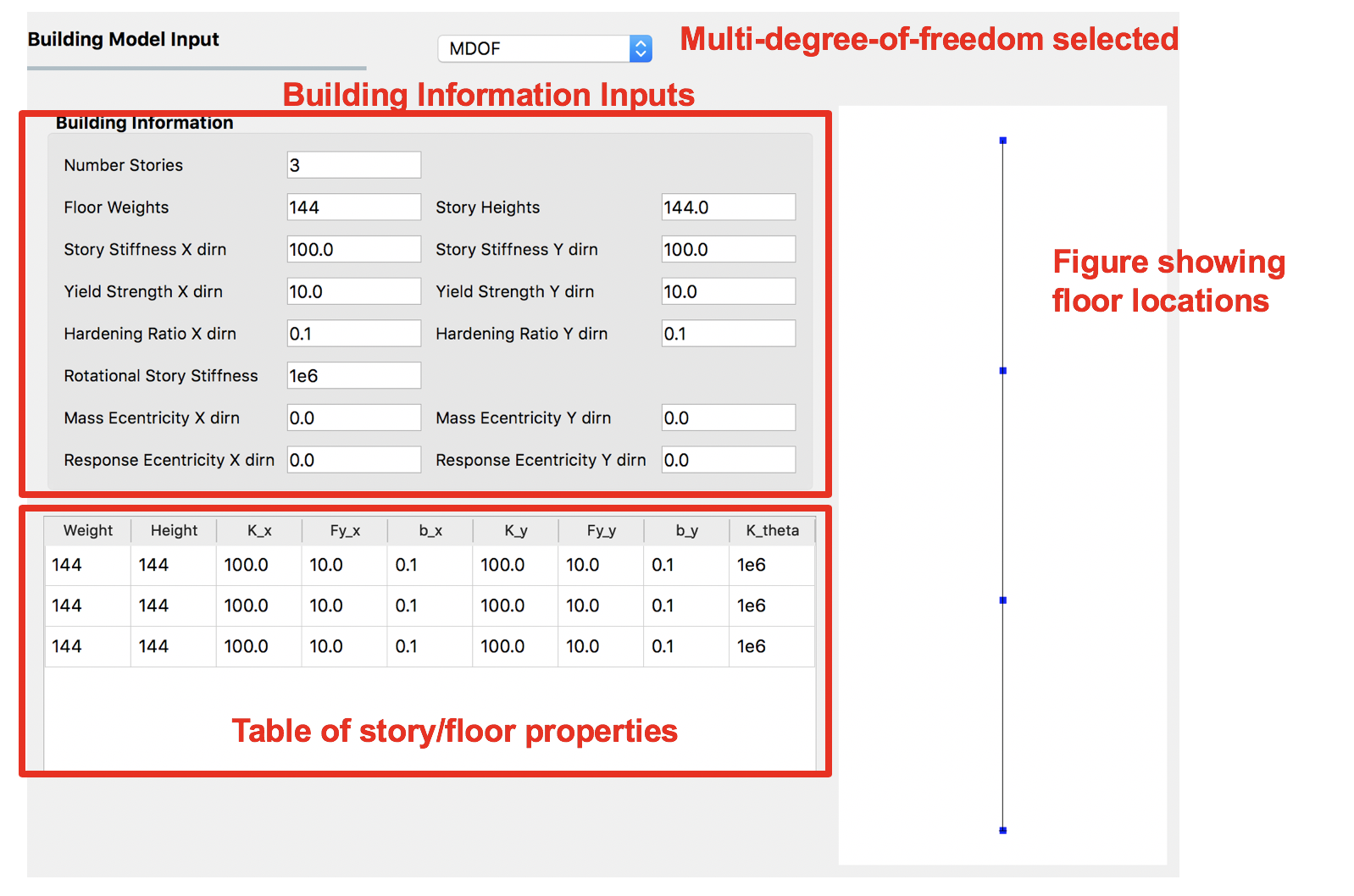
Fig. 2.3.1.1 Multiple degrees of freedom (MDOF) building model generator.
The user can create random variables if they enter a valid string instead of a number in the entry fields for any entry except for the Number of floors. The variable name entered will appear as a random variable in the UQ panel; it is there that the user must specify the distribution associated with the random variable.
2.3.2. OpenSees
This panel is for users with an existing OpenSees model of a building that performs a gravity analysis. Now they wish to subject that building model to one of the EVT options provided. The input panel for this option is shown in Fig. 2.3.2.1. Users need to provide three pieces of information:
Main OpenSees Script: The main script that contains the building model. This script should build a model and perform any gravity analysis of the building required before the event is applied.
Response Nodes: A list of node numbers that define a column line of interest for which the responses will be determined. The column nodes should be in order from ground floor to roof. The EDP workflow application uses this information to decide nodes at which displacement, acceleration, and story drifts are calculated.
An entry for the dimension of the model (i.e., 2D or 3D). This information is used when loads are applied.
Entry for the number of degrees of freedom at each node in the model.
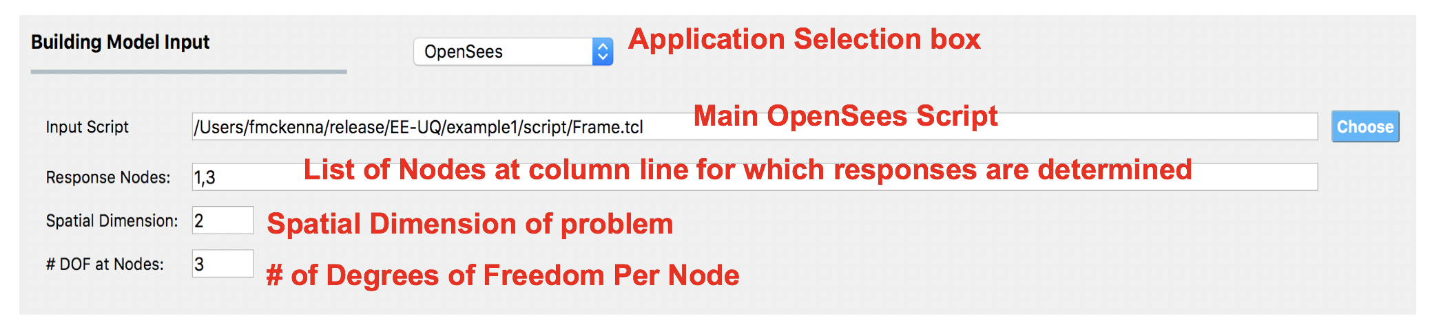
Fig. 2.3.2.1 OpenSees Model.
In OpenSees, there is an option to set variables to have specific values using the pset command, e.g pset a 5.0 will set the variable a to have a value 5 in the OpenSees script. In HydroUQ, any variable found in the main script to be set using the pset command will be assumed to be a random variable. When a new main script is loaded, all variables set with pset will appear as random variables in the UQ panel.
2.3.3. Steel Building Model (AutoSDA)
This module should not be used for tsunami/storm surge hazards but only valid for earthquake events.