4.1. Stochastic Wave Loading on a Frame Structure - JONSWAP Spectra
Problem files |
4.1.1. Overview
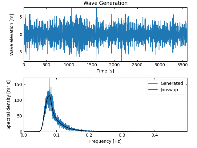
This local workflow example uses HydroUQ to apply basic uncertainty quantification methods— Forward, Sensitivity, Reliability, and Surrogate—to the response of a simple structure subjected to stochastic wave loading drawn from a JONSWAP spectrum.
Warning
The JONSWAP spectra is limited in its applicability. It was semi-empirically developed based on data from field measurements in the North Sea. In this example, we imagine it as being applied to an off-shore structure in the North Atlantic, perhaps off the coast of Maine or Norway during appropriate sea-states. Ultimately JONSWAP is a placeholder spectra that advanced users can replace with their own.
Note
Units must be used consistently across GI, SIM, EVT, and FEM panels. If not otherwise specified, adopt your project’s standard (e.g., kips-in-s or N-m-s) and keep all inputs consistent. We leave this double-checking to the user as an exercise in better understanding the OpenSees structural and JONSWAP wave spectra models.
4.1.2. Set-Up
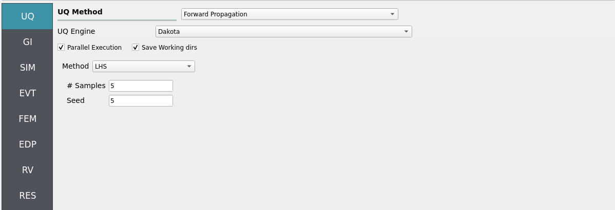
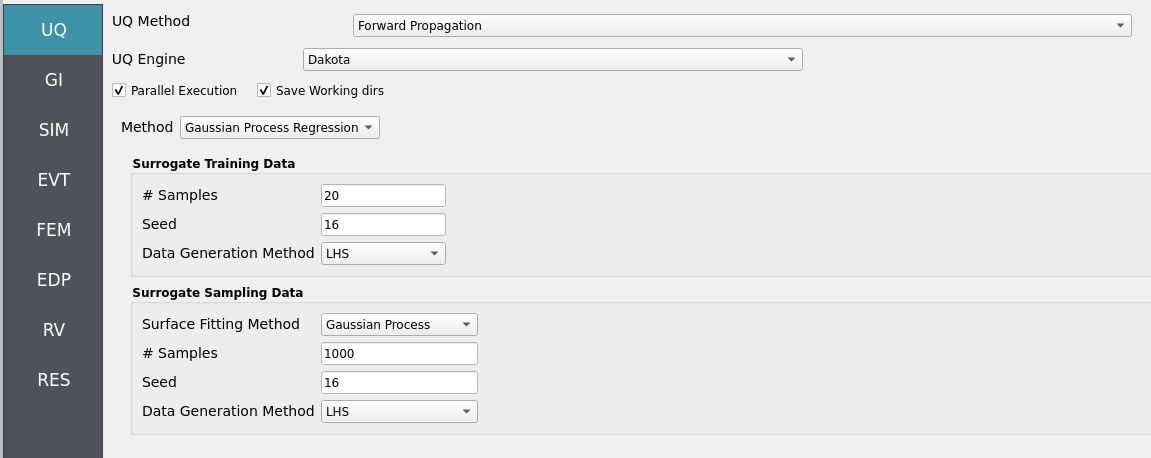
4.1.2.1. Step 1: UQ
Configure UQ to explore structural/material and loading uncertainties.
Engine: Dakota
Forward Propagation Sample method (e.g., LHS) with
samples(e.g.,40) andseed(e.g.,1) for repeatability.
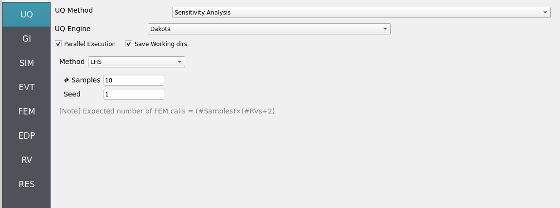
Sensitivity: choose a sampling method (e.g., Monte-Carlo or Latin Hyper Cube) to aid in ranking influence of
fc,fy, andE.
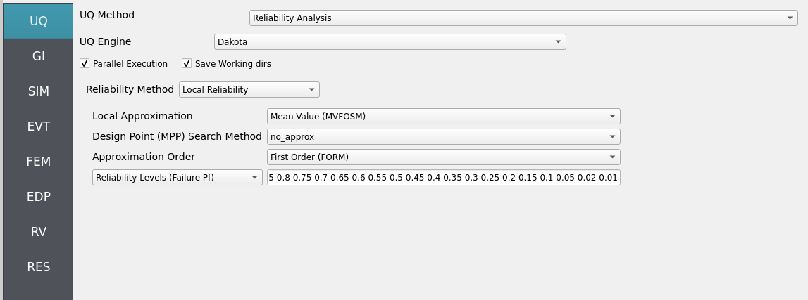
Reliability: choose a suitable method (e.g., FORM/SORM or importance sampling) and define a limit state (e.g., peak drift or member demand ratio).
Surrogate: choose a Gaussian process regression (GPR) or polynomial chaos expansion (PCE) model to build a reduced-order model for efficient uncertainty quantification.
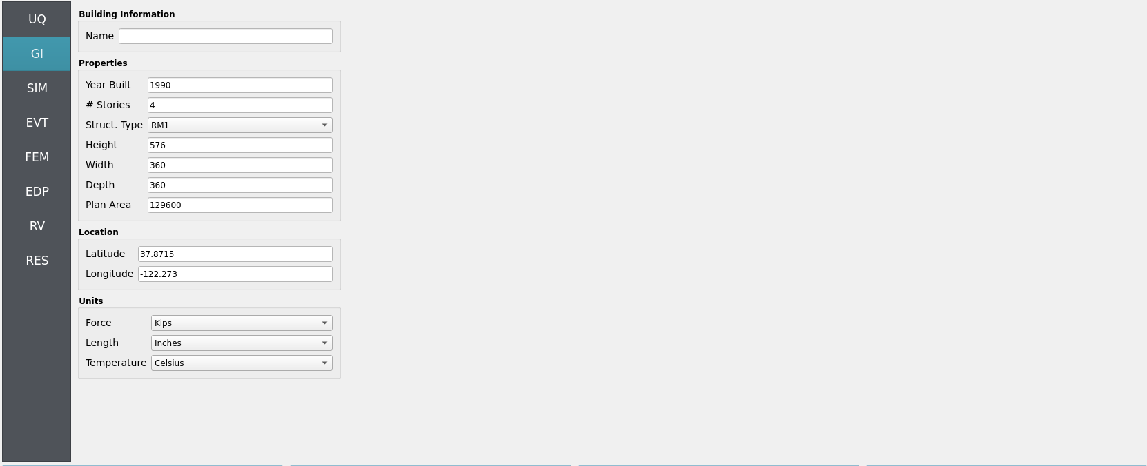
4.1.2.2. Step 2: GI
Set General Information and Units. Ensure that length/time units are consistent with the JONSWAP parameters (Tp, dt, T) and the solver’s integration settings.
Project name:
hdro-0005Location/metadata: optional
Units: select your consistent set (e.g., kips-in-s or N-m-s)
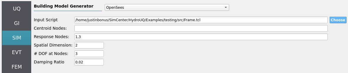
4.1.2.3. Step 3: SIM
The structural model is as follows: a 2D, 3-DOF OpenSees portal frame in OpenSees, OpenSees.
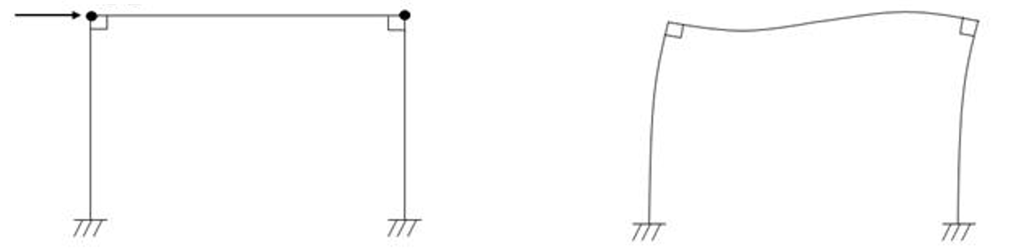
Fig. 4.1.2.3.1 2D 3-DOF portal frame under stochastic wave loading (JONSWAP)
For the OpenSees generator the following model script, Frame.tcl , is used:
Click to expand the OpenSees input file used for this example
  1# Create ModelBuilder (with two-dimensions and 3 DOF/node)
  2
  3model basic -ndm 2 -ndf 3
  4
  5set width    360
  6set height   144
  7
  8node  1       0.0     0.0
  9node  2    $width     0.0
 10node  3       0.0 $height
 11node  4    $width $height
 12
 13fix   1     1    1    1
 14fix   2     1    1    1
 15
 16# Concrete ( Youngs Modulus, Yield Strength, and Compressive Strength)
 17pset fc 6.0
 18pset fy 60.0
 19pset E 30000.0
 20uniaxialMaterial Concrete01  1  -$fc  -0.004   -5.0     -0.014
 21uniaxialMaterial Concrete01  2  -5.0   -0.002   0.0     -0.006
 22
 23# STEEL
 24uniaxialMaterial Steel01  3  $fy $E 0.01
 25
 26set colWidth 15
 27set colDepth 24
 28set cover  1.5
 29set As    0.60;     # area of no. 7 bars
 30set y1 [expr $colDepth/2.0]
 31set z1 [expr $colWidth/2.0]
 32
 33section Fiber 1 {
 34
 35    # Create the concrete core fibers
 36    patch rect 1 10 1 [expr $cover-$y1] [expr $cover-$z1] [expr $y1-$cover] [expr $z1-$cover]
 37
 38    # Create the concrete cover fibers (top, bottom, left, right)
 39    patch rect 2 10 1  [expr -$y1] [expr $z1-$cover] $y1 $z1
 40    patch rect 2 10 1  [expr -$y1] [expr -$z1] $y1 [expr $cover-$z1]
 41    patch rect 2  2 1  [expr -$y1] [expr $cover-$z1] [expr $cover-$y1] [expr $z1-$cover]
 42    patch rect 2  2 1  [expr $y1-$cover] [expr $cover-$z1] $y1 [expr $z1-$cover]
 43
 44    # Create the reinforcing fibers (left, middle, right)
 45    layer straight 3 3 $As [expr $y1-$cover] [expr $z1-$cover] [expr $y1-$cover] [expr $cover-$z1]
 46    layer straight 3 2 $As 0.0 [expr $z1-$cover] 0.0 [expr $cover-$z1]
 47    layer straight 3 3 $As [expr $cover-$y1] [expr $z1-$cover] [expr $cover-$y1] [expr $cover-$z1]
 48
 49}
 50
 51
 52# Define column elements
 53# ----------------------
 54
 55# Geometry of column elements
 56#                tag
 57
 58geomTransf Corotational 1
 59
 60# Number of integration points along length of element
 61set np 5
 62
 63# Create the coulumns using Beam-column elements
 64#               e            tag ndI ndJ nsecs secID transfTag
 65set eleType dispBeamColumn
 66element $eleType  1   1   3   $np    1       1
 67element $eleType  2   2   4   $np    1       1
 68
 69# Define beam elment
 70# -----------------------------
 71
 72# Geometry of column elements
 73#                tag
 74geomTransf Linear 2
 75
 76# Create the beam element
 77#                          tag ndI ndJ     A       E    Iz   transfTag
 78element elasticBeamColumn   3   3   4    360    4030  8640    2
 79
 80# Define gravity loads
 81# --------------------
 82
 83# Set a parameter for the axial load
 84set P 180;                # 10% of axial capacity of columns
 85
 86# Create a Plain load pattern with a Linear TimeSeries
 87pattern Plain 1 "Linear" {
 88
 89        # Create nodal loads at nodes 3 & 4
 90	#    nd    FX          FY  MZ
 91	load  3   0.0  [expr -$P] 0.0
 92	load  4   0.0  [expr -$P] 0.0
 93}
 94
 95# ------------------------------
 96# Start of analysis generation
 97# ------------------------------
 98
 99# Create the system of equation, a sparse solver with partial pivoting
100system ProfileSPD
101
102# Create the constraint handler, the transformation method
103constraints Transformation
104
105# Create the DOF numberer, the reverse Cuthill-McKee algorithm
106numberer RCM
107
108# Create the convergence test, the norm of the residual with a tolerance of
109# 1e-12 and a max number of iterations of 10
110test NormDispIncr 1.0e-12  10 3
111
112# Create the solution algorithm, a Newton-Raphson algorithm
113algorithm Newton
114
115# Create the integration scheme, the LoadControl scheme using steps of 0.1
116integrator LoadControl 0.1
117
118# Create the analysis object
119analysis Static
120
121# ------------------------------
122# End of analysis generation
123# ------------------------------
124
125# perform the gravity load analysis, requires 10 steps to reach the load level
126analyze 10
127
128loadConst -time 0.0
129
130# ----------------------------------------------------
131# End of Model Generation & Initial Gravity Analysis
132# ----------------------------------------------------
133
134
135# ----------------------------------------------------
136# Start of additional modelling for dynamic loads
137# ----------------------------------------------------
138
139# Define nodal mass in terms of axial load on columns
140set g 386.4
141set m [expr $P/$g];       # expr command to evaluate an expression
142
143#    tag   MX   MY   RZ
144mass  3    $m   $m    0
145mass  4    $m   $m    0
Note
The first lines containing pset in an OpenSees tcl file will be read by the application when the file is selected. The application will autopopulate the random variables in the RV panel with these same variable names.
These variable names (fc, fy, E) are recognized in Frame.tcl due to use of the pset command instead of set. This is so that RV picks them up automatically. You can try adding new RV parameters in the same way.
Uncertain properties (treated as RVs; see Step 7):
fc: mean6, stdev0.06fy: mean60, stdev0.6E: mean30000, stdev300
4.1.2.4. Step 4: EVT
Load Generator: Stochastic Waves - JONSWAP Spectra.
Set hydrodynamic parameters:
H = 8.1(significant wave height)Tp = 12.7(peak period)dt = 1(time step)T = 300(duration)Seed = 1(random seed)
Force model: we assume a monopile-like structure under Wheeler-corrected Morison drag. The monopile possesses a coefficient of drag (Cd) and drag area (Ad) of:
Cd = 2.1(coefficient of drag)Ad = 1(drag area)
If you treat wave descriptive parameters as deterministic in this example, keep them as literals; otherwise enter alphabetic variable names to expose them in RV. You may try changing the peak period or significant wave height, for instance, to a random variable.
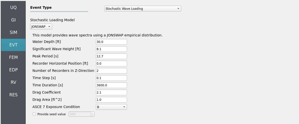
Important
Two recorders were requested in the EVT panel: one will map its recorded loads to the base node of the OpenSees structure defined in the SIM and FEM panels, whereas the other will map loads to the remaining node. More recorders can be requested to increase loading resolution and extrapolate to multi-story structures if your designated OpenSees model is equipped with more mappable nodes.
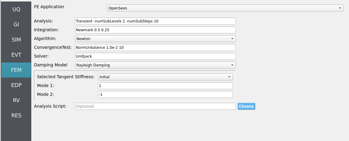
4.1.2.5. Step 5: FEM
Solver: OpenSees dynamic analysis. Defaults are usually sufficient; verify the following are consistent with your units, structural model, and anticipated load pattern:
Integration/time-step tolerance compatible with event
Algorithm and convergence tolerances suitable for nonlinear response
Damping model as needed (e.g., Rayleigh)
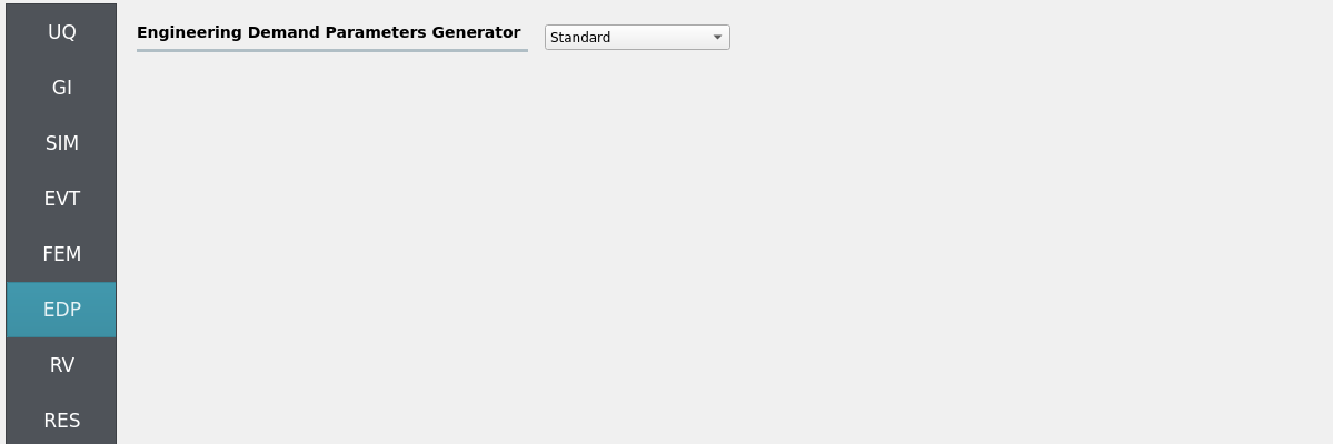
4.1.2.6. Step 6: EDP
We will leave selection of engineering demand parameters (EDPs) as the standard set. This defines the following engineering demand parameters (EDPs) of interest which our workflow will solve for:
Peak Floor Acceleration (PFA)
Root Mean Square Floor Acceleration (RMSA)
Peak Floor Displacement (PFD)
Peak Interstory Drift (PID)
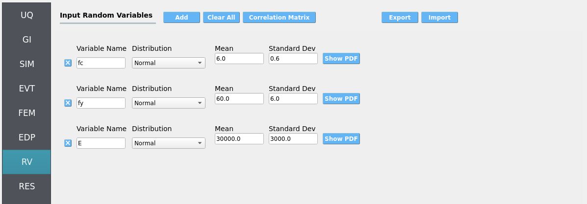
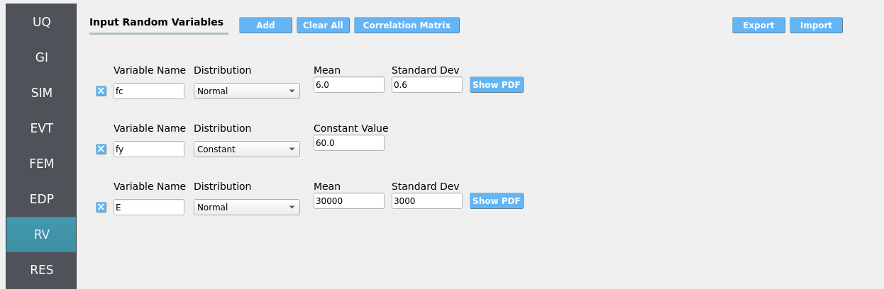
4.1.2.7. Step 7: RV
Define the distributions for structural uncertainties:
fc: Normal (mean6, stdev0.06)fy: Normal (mean60, stdev0.6)E: Normal (mean30000, stdev300)
Note
If you chose to promote any hydrodynamic parameters in the Event to Random Variables, ensure they are defined here.
Warning
Do not leave distributions as constant when using the Dakota UQ engine unless the variable is intentionally deterministic for this study.
Each uncertainty quantification approach uses slightly different random variable definitions. They are as follow:
Forward Sampling
Sensitivity Analysis
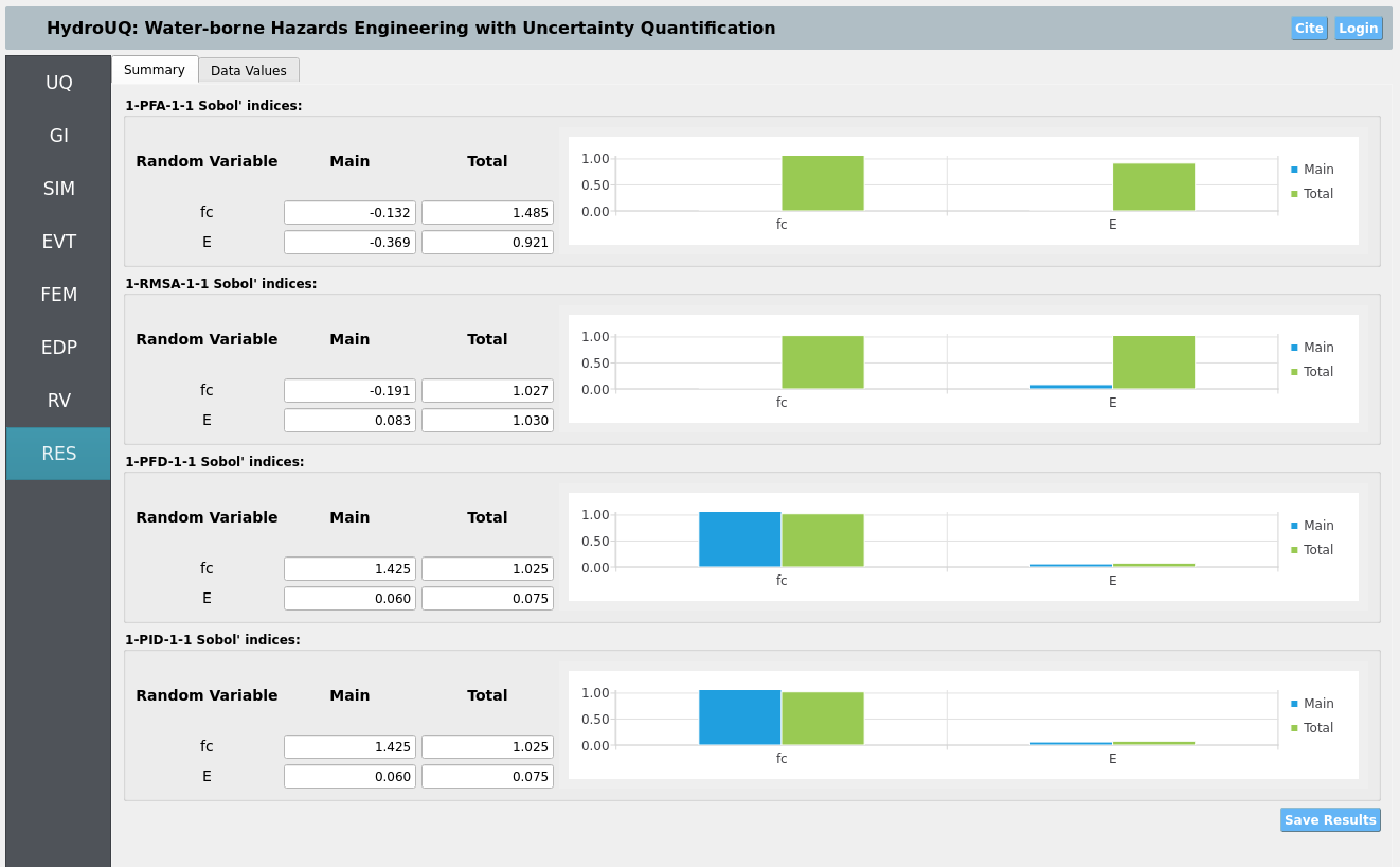
Important
One parameter is kept constant for the sensitivity analysis as a sanity check. The constant variable should have little to no influence on the final results, which should be reflected in the reported Sobol indices.
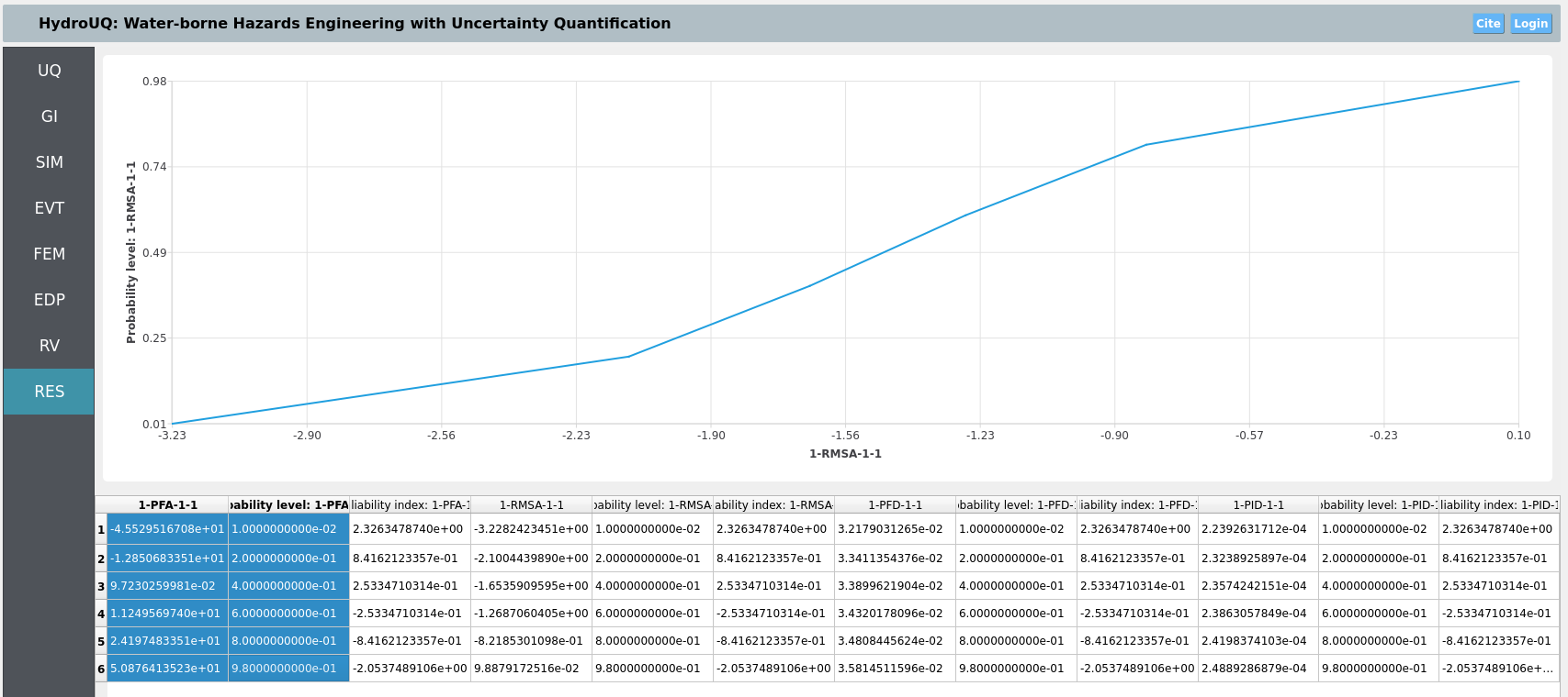
Reliability Analysis
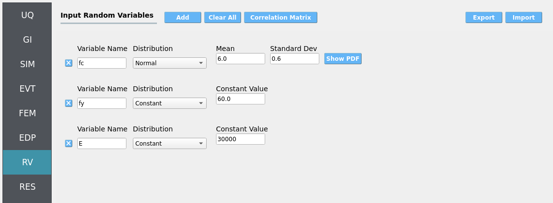
Important
This reliability analysis approach only allows for one random variable to be treated as uncertain at a time. The others are kept as constants.
Surrogate Modeling
4.1.3. Simulation
This workflow is designed for local execution. It should be compatible with your personal Mac, Linux, or Windows machine. Click RUN. When complete, usually within a few minutes, the RES panel opens:
Also, this workflow may be ran remotely using the RUN at DesignSafe option. This isn’t recommended due to the light computational burden of this example, but it is an option for those with DesignSafe accounts if they would like to run this case at a larger scale on the Stampede3 supercomputer instead.
Warning
Only ask for what you need in terms of recorder count, time-step size, random variables, and UQ samples. Otherwise, you will end up with massive amounts of data which can slow simulations due to I/O constraints.
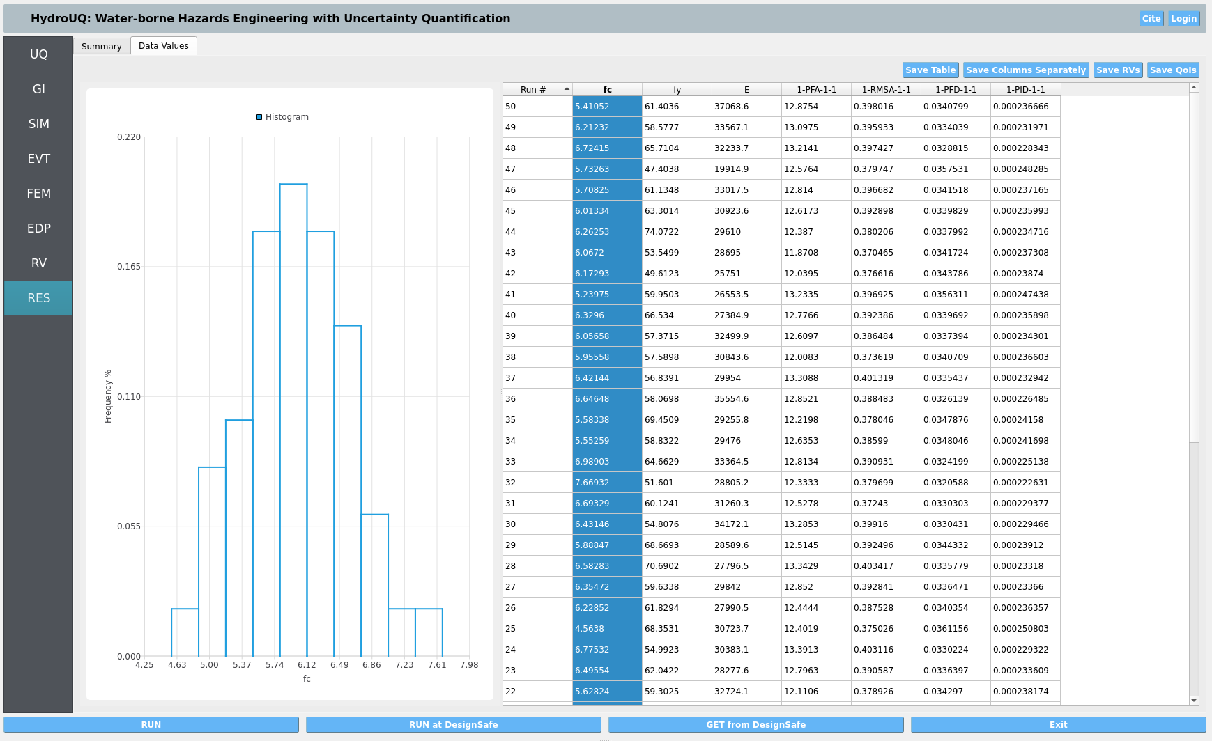
4.1.4. Analysis
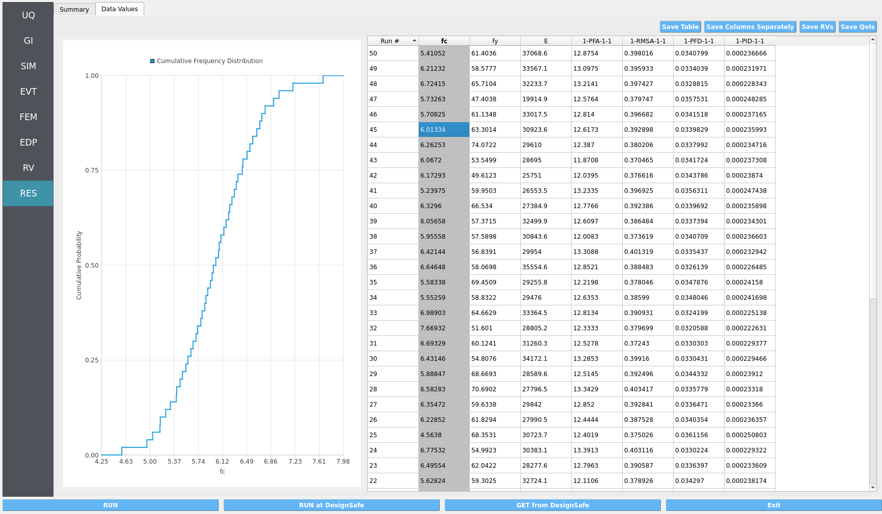
Returning to our primary HydroUQ workflow, which concerns uncertainty in structural response, we may now view the final results in the RES tab.
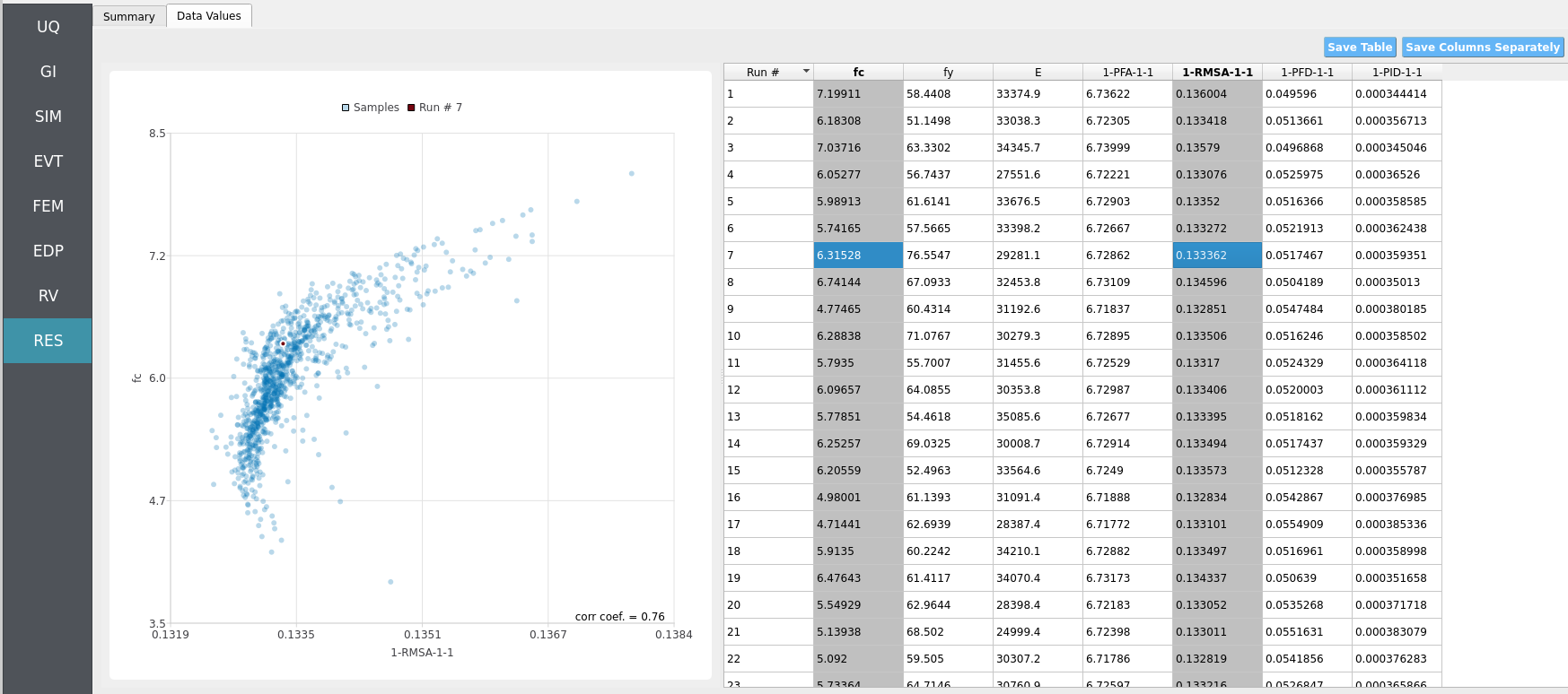
Forward: summary statistics and correlations across realizations.
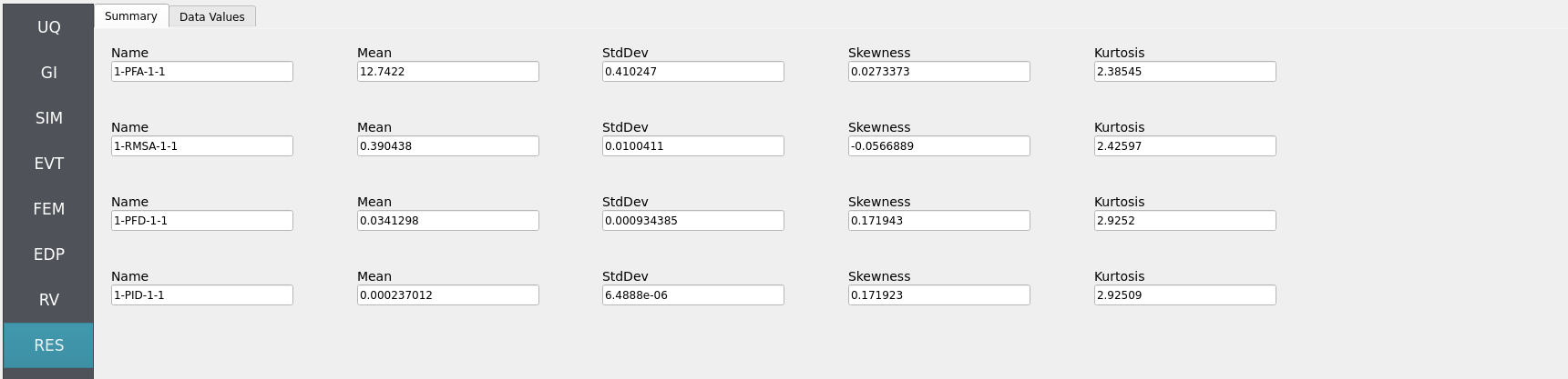
Note
In the Data tab, left- and right-click column headers to change plot axes; selecting a single column with both clicks displays frequency and CDF plots.
Sensitivity: variable influence ranking (e.g., fc vs fy vs E).
Reliability: probability of exceeding the user-defined limit state (e.g., peak interstory drift over a threshold).
Surrogate: reduced-order models (e.g., Gaussian process regression) for efficient uncertainty quantification.
For more advanced analysis, export results as a CSV file by clicking Save Table on the upper-right of the application window. This will save the independent and dependent variable data. I.e., the Random Variables you defined and the Engineering Demand Parameters determined from the structural response per each simulation.
To save your simulation configuration with results included, click File / Save As and specify a location for the HydroUQ JSON input file to be recorded to. You may then reload the file at a later time by clicking File / Open. You may also send it to others by email or place it in an online repository for research reproducibility. This example’s input file is viewable at Reproducibility.
To directly share your simulation job and results in HydroUQ with other DesignSafe users, click GET from DesignSafe. Then, navigate to the row with your job and right-click it. Select Share Job. You may then enter the DesignSafe username or usernames (comma-separated) to share with.
Important
Sharing a job requires that the job was initially ran with an Archive System ID (listed in the GET from DesignSafe table’s columns) that is not designsafe.storage.default. Any other Archive System ID allows for sharing with DesignSafe members on the associated project. See Jobs for more details.
4.1.5. Conclusions
This example demonstrates HydroUQ’s ability to drive Forward, Sensitivity, Reliability, and Surrogate analyses for a simple OpenSees frame under JONSWAP-based stochastic wave loading with a Morison-type drag model. The results indicate which material property uncertainties (fc, fy, E) most strongly influence response, and provide an estimated probability of exceeding a chosen performance limit.
4.1.6. Reproducibility
Random seed(s):
1for forward, sensitivity, and reliability analysis,16for surrogate modeling. (UQ/event)Model file:
Frame.tclApp version: HydroUQ v4.2.0
System: Your personal Mac, Linux, or Windows machine. Also TACC’s Stampede3 supercomputer using a DesignSafe account and allocation.
Input: The HydroUQ input files are as follows: input.json , input_Sensitivity.json, input_Reliability.json , input_GP.json :
Click to expand the HydroUQ forward sampling input file used for this example
  1{
  2    "Applications": {
  3        "EDP": {
  4            "Application": "StandardEDP",
  5            "ApplicationData": {
  6            }
  7        },
  8        "Events": [
  9            {
 10                "Application": "StochasticWave",
 11                "ApplicationData": {
 12                },
 13                "EventClassification": "Hydro"
 14            }
 15        ],
 16        "Modeling": {
 17            "Application": "OpenSeesInput",
 18            "ApplicationData": {
 19                "fileName": "Frame.tcl",
 20                "filePath": "{Current_Dir}/."
 21            }
 22        },
 23        "Simulation": {
 24            "Application": "OpenSees-Simulation",
 25            "ApplicationData": {
 26            }
 27        },
 28        "UQ": {
 29            "Application": "Dakota-UQ",
 30            "ApplicationData": {
 31            }
 32        }
 33    },
 34    "DefaultValues": {
 35        "driverFile": "driver",
 36        "edpFiles": [
 37            "EDP.json"
 38        ],
 39        "filenameAIM": "AIM.json",
 40        "filenameDL": "BIM.json",
 41        "filenameEDP": "EDP.json",
 42        "filenameEVENT": "EVENT.json",
 43        "filenameSAM": "SAM.json",
 44        "filenameSIM": "SIM.json",
 45        "rvFiles": [
 46            "AIM.json",
 47            "SAM.json",
 48            "EVENT.json",
 49            "SIM.json"
 50        ],
 51        "workflowInput": "scInput.json",
 52        "workflowOutput": "EDP.json"
 53    },
 54    "EDP": {
 55        "type": "StandardEDP"
 56    },
 57    "Events": [
 58        {
 59            "EventClassification": "Hydro",
 60            "dragArea": 1,
 61            "dragCoefficient": 2.1,
 62            "exposureCategory": "NATO 5",
 63            "peakPeriod": 12.7,
 64            "recorderCountZ": 2,
 65            "recorderOriginX": 0,
 66            "significantWaveHeight": 8.1,
 67            "timeDuration": 300.0,
 68            "timeStep": 1.0,
 69            "type": "StochasticWave",
 70            "waterDepth": 30.0,
 71            "tidalSLR": 3.0,
 72            "stormSurgeSLR": 2.0,
 73            "climateChangeSLR": 1.0,
 74            "seed": 1
 75        }
 76    ],
 77    "GeneralInformation": {
 78        "NumberOfStories": 1,
 79        "PlanArea": 129600,
 80        "StructureType": "RM1",
 81        "YearBuilt": 2025,
 82        "depth": 360,
 83        "height": 576,
 84        "location": {
 85            "latitude": 37.8715,
 86            "longitude": -122.273
 87        },
 88        "name": "",
 89        "planArea": 129600,
 90        "stories": 1,
 91        "units": {
 92            "force": "kips",
 93            "length": "in",
 94            "temperature": "C",
 95            "time": "sec"
 96        },
 97        "width": 360
 98    },
 99    "Modeling": {
100        "centroidNodes": [
101            1,
102            3
103        ],
104        "dampingRatio": 0.02,
105        "ndf": 3,
106        "ndm": 2,
107        "randomVar": [
108            {
109                "name": "fc",
110                "value": "RV.fc"
111            },
112            {
113                "name": "fy",
114                "value": "RV.fy"
115            },
116            {
117                "name": "E",
118                "value": "RV.E"
119            }
120        ],
121        "responseNodes": [
122            1,
123            3
124        ],
125        "type": "OpenSeesInput"
126    },
127    "Simulation": {
128        "Application": "OpenSees-Simulation",
129        "algorithm": "Newton",
130        "analysis": "Transient -numSubLevels 2 -numSubSteps 10",
131        "convergenceTest": "NormUnbalance 1.0e-2 10",
132        "dampingModel": "Rayleigh Damping",
133        "firstMode": 1,
134        "integration": "Newmark 0.5 0.25",
135        "modalRayleighTangentRatio": 0,
136        "numModesModal": -1,
137        "rayleighTangent": "Initial",
138        "secondMode": -1,
139        "solver": "Umfpack"
140    },
141    "UQ": {
142        "parallelExecution": true,
143        "samplingMethodData": {
144            "method": "LHS",
145            "samples": 40,
146            "seed": 1
147        },
148        "saveWorkDir": false,
149        "uqEngine": "Dakota",
150        "uqType": "Forward Propagation"
151    },
152    "correlationMatrix": [
153        1,
154        0,
155        0,
156        0,
157        1,
158        0,
159        0,
160        0,
161        1
162    ],
163    "localAppDir": "/home/justinbonus/SimCenter/HydroUQ/build",
164    "randomVariables": [
165        {
166            "distribution": "Normal",
167            "inputType": "Parameters",
168            "mean": 6,
169            "name": "fc",
170            "refCount": 1,
171            "stdDev": 0.6,
172            "value": "RV.fc",
173            "variableClass": "Uncertain"
174        },
175        {
176            "distribution": "Normal",
177            "inputType": "Parameters",
178            "mean": 60,
179            "name": "fy",
180            "refCount": 1,
181            "stdDev": 6,
182            "value": "RV.fy",
183            "variableClass": "Uncertain"
184        },
185        {
186            "distribution": "Normal",
187            "inputType": "Parameters",
188            "mean": 30000,
189            "name": "E",
190            "refCount": 1,
191            "stdDev": 3000,
192            "value": "RV.E",
193            "variableClass": "Uncertain"
194        }
195    ],
196    "remoteAppDir": "/Users/fmckenna/NHERI/SimCenterBackendApplications",
197    "runType": "runningLocal",
198    "workingDir": "/home/justinbonus/Documents/HydroUQ/LocalWorkDir"
199}
Click to expand the HydroUQ sensitivity analysis input file used for this example
1{
2 "Applications": {
3 "EDP": {
4 "Application": "StandardEDP",
5 "ApplicationData": {
6 }
7 },
8 "Events": [
9 {
10 "Application": "StochasticWave",
11 "ApplicationData": {
12 },
13 "EventClassification": "Hydro"
14 }
15 ],
16 "Modeling": {
17 "Application": "OpenSeesInput",
18 "ApplicationData": {
19 "fileName": "Frame.tcl",
20 "filePath": "{Current_Dir}/."
21 }
22 },
23 "Simulation": {
24 "Application": "OpenSees-Simulation",
25 "ApplicationData": {
26 }
27 },
28 "UQ": {
29 "Application": "Dakota-UQ",
30 "ApplicationData": {
31 }
32 }
33 },
34 "DefaultValues": {
35 "driverFile": "driver",
36 "edpFiles": [
37 "EDP.json"
38 ],
39 "filenameAIM": "AIM.json",
40 "filenameDL": "BIM.json",
41 "filenameEDP": "EDP.json",
42 "filenameEVENT": "EVENT.json",
43 "filenameSAM": "SAM.json",
44 "filenameSIM": "SIM.json",
45 "rvFiles": [
46 "AIM.json",
47 "SAM.json",
48 "EVENT.json",
49 "SIM.json"
50 ],
51 "workflowInput": "scInput.json",
52 "workflowOutput": "EDP.json"
53 },
54 "EDP": {
55 "type": "StandardEDP"
56 },
57 "Events": [
58 {
59 "EventClassification": "Hydro",
60 "climateChangeSLR": 1,
61 "dragArea": 1,
62 "dragCoefficient": 2.1,
63 "exposureCategory": "NATO 5",
64 "peakPeriod": 12.7,
65 "recorderCountZ": 2,
66 "recorderOriginX": 0,
67 "seed": 1,
68 "significantWaveHeight": 8.1,
69 "stormSurgeSLR": 2,
70 "tidalSLR": 3,
71 "timeDuration": 300.0,
72 "timeStep": 1.0,
73 "type": "StochasticWave",
74 "waterDepth": 30
75 }
76 ],
77 "GeneralInformation": {
78 "NumberOfStories": 1,
79 "PlanArea": 129600,
80 "StructureType": "RM1",
81 "YearBuilt": 2025,
82 "depth": 360,
83 "height": 576,
84 "location": {
85 "latitude": 37.8715,
86 "longitude": -122.273
87 },
88 "name": "",
89 "planArea": 129600,
90 "stories": 1,
91 "units": {
92 "force": "kips",
93 "length": "in",
94 "temperature": "C",
95 "time": "sec"
96 },
97 "width": 360
98 },
99 "Modeling": {
100 "centroidNodes": [
101 1,
102 3
103 ],
104 "dampingRatio": 0.02,
105 "ndf": 3,
106 "ndm": 2,
107 "randomVar": [
108 {
109 "name": "fc",
110 "value": "RV.fc"
111 },
112 {
113 "name": "fy",
114 "value": "RV.fy"
115 },
116 {
117 "name": "E",
118 "value": "RV.E"
119 }
120 ],
121 "responseNodes": [
122 1,
123 3
124 ],
125 "type": "OpenSeesInput"
126 },
127 "QoIlist": [
128 "1-PFA-1-1 Sobol' indices:",
129 "1-RMSA-1-1 Sobol' indices:",
130 "1-PFD-1-1 Sobol' indices:",
131 "1-PID-1-1 Sobol' indices:"
132 ],
133 "RVlist": [
134 "fc",
135 "fy",
136 "E"
137 ],
138 "Simulation": {
139 "Application": "OpenSees-Simulation",
140 "algorithm": "Newton",
141 "analysis": "Transient -numSubLevels 2 -numSubSteps 10",
142 "convergenceTest": "NormUnbalance 1.0e-2 10",
143 "dampingModel": "Rayleigh Damping",
144 "firstMode": 1,
145 "integration": "Newmark 0.5 0.25",
146 "modalRayleighTangentRatio": 0,
147 "numModesModal": -1,
148 "rayleighTangent": "Initial",
149 "secondMode": -1,
150 "solver": "Umfpack"
151 },
152 "UQ": {
153 "parallelExecution": true,
154 "samplingMethodData": {
155 "method": "LHS",
156 "samples": 10,
157 "seed": 1
158 },
159 "saveWorkDir": false,
160 "uqEngine": "Dakota",
161 "uqType": "Sensitivity Analysis"
162 },
163 "localAppDir": "/home/justinbonus/SimCenter/HydroUQ/build",
164 "numQoI": 4,
165 "numRV": 3,
166 "randomVariables": [
167 {
168 "distribution": "Normal",
169 "inputType": "Parameters",
170 "mean": 6,
171 "name": "fc",
172 "refCount": 1,
173 "stdDev": 0.6,
174 "value": "RV.fc",
175 "variableClass": "Uncertain"
176 },
177 {
178 "distribution": "Normal",
179 "inputType": "Parameters",
180 "mean": 60,
181 "name": "fy",
182 "refCount": 1,
183 "stdDev": 6,
184 "value": "RV.fy",
185 "variableClass": "Uncertain"
186 },
187 {
188 "distribution": "Normal",
189 "inputType": "Parameters",
190 "mean": 30000,
191 "name": "E",
192 "refCount": 1,
193 "stdDev": 3000,
194 "value": "RV.E",
195 "variableClass": "Uncertain"
196 }
197 ],
198 "remoteAppDir": "/home/justinbonus/SimCenter/HydroUQ/build",
199 "resultType": "DakotaResultsSensitivity",
200 "runType": "runningLocal",
201 "sobols_main": [
202 -0.26811465122,
203 0,
204 -0.20107572198,
205 -0.26160043411,
206 0,
207 -0.081846525429,
208 0.6540160986,
209 0,
210 0.12022198151,
211 0.65398604822,
212 0,
213 0.12020668405
214 ],
215 "sobols_tot": [
216 0.67290625318,
217 0,
218 1.1369047803,
219 0.63298578083,
220 0,
221 1.1150605194,
222 0.77084202611,
223 0,
224 0.087311491526,
225 0.77082745389,
226 0,
227 0.087307058611
228 ],
229 "spreadsheet": {
230 "data": [
231 1,
232 5.495039505,
233 73.72557645,
234 30693.88623,
235 12.4454,
236 0.13264,
237 0.0339714,
238 0.000235912,
239 2,
240 6.548849595,
241 57.87294814,
242 25898.72955,
243 12.2277,
244 0.129974,
245 0.0330572,
246 0.000229564,
247 3,
248 5.942466727,
249 63.63946781,
250 32154.30312,
251 12.2056,
252 0.129644,
253 0.0331484,
254 0.000230197,
255 4,
256 4.778111896,
257 57.58904126,
258 24749.23619,
259 11.7781,
260 0.122945,
261 0.0358595,
262 0.000249024,
263 5,
264 6.166517367,
265 68.04102428,
266 28718.39426,
267 11.7632,
268 0.122284,
269 0.0332515,
270 0.000230913,
271 6,
272 6.344864594,
273 60.50477866,
274 33147.66784,
275 11.9378,
276 0.124311,
277 0.0324741,
278 0.000225515,
279 7,
280 6.2629468,
281 67.58638787,
282 30793.10705,
283 12.3037,
284 0.131204,
285 0.0328657,
286 0.000228234,
287 8,
288 5.607321171,
289 47.79408428,
290 29576.12266,
291 12.6904,
292 0.137237,
293 0.0339485,
294 0.000235753,
295 9,
296 7.454140561,
297 56.36246875,
298 29949.24597,
299 12.4518,
300 0.132344,
301 0.0313773,
302 0.000217898,
303 10,
304 6.006943911,
305 55.16610547,
306 34765.33497,
307 11.8749,
308 0.123536,
309 0.0327446,
310 0.000227393,
311 11,
312 5.48776321,
313 65.20178881,
314 27367.83496,
315 12.2787,
316 0.130064,
317 0.0344078,
318 0.000238943,
319 12,
320 5.859360877,
321 59.6496857,
322 28020.12276,
323 12.0148,
324 0.126972,
325 0.0337774,
326 0.000234565,
327 13,
328 5.340963548,
329 54.42097013,
330 30337.07483,
331 11.644,
332 0.121296,
333 0.034244,
334 0.000237806,
335 14,
336 6.758038954,
337 62.68694978,
338 26870.20872,
339 12.1251,
340 0.127784,
341 0.0326515,
342 0.000226747,
343 15,
344 5.711160867,
345 64.46346789,
346 31500.15086,
347 12.2478,
348 0.130743,
349 0.033557,
350 0.000233035,
351 16,
352 6.470415059,
353 61.84652402,
354 32617.05287,
355 12.3476,
356 0.131543,
357 0.0323664,
358 0.000224767,
359 17,
360 6.872027891,
361 50.94667071,
362 29051.25988,
363 12.2589,
364 0.129827,
365 0.0322414,
366 0.000223899,
367 18,
368 5.847917235,
369 58.50117474,
370 36398.17963,
371 11.9153,
372 0.124213,
373 0.032769,
374 0.000227562,
375 19,
376 6.105563351,
377 61.45336567,
378 27639.31024,
379 12.6584,
380 0.136143,
381 0.0334706,
382 0.000232435,
383 20,
384 5.230587576,
385 53.3611634,
386 31590.0753,
387 12.7371,
388 0.138427,
389 0.0342471,
390 0.000237827,
391 21,
392 5.269006652,
393 63.72444535,
394 33854.64981,
395 12.6175,
396 0.135812,
397 0.0339022,
398 0.000235432,
399 22,
400 6.275252789,
401 61.05647063,
402 28700.00958,
403 12.1279,
404 0.128188,
405 0.0331008,
406 0.000229867,
407 23,
408 6.040683688,
409 65.44804922,
410 33033.94424,
411 12.7558,
412 0.13733,
413 0.032905,
414 0.000228507,
415 24,
416 5.824135528,
417 56.08191809,
418 26260.91367,
419 12.1495,
420 0.129533,
421 0.0340509,
422 0.000236465,
423 25,
424 6.469806732,
425 64.97246561,
426 25908.30721,
427 12.667,
428 0.135981,
429 0.0331668,
430 0.000230325,
431 26,
432 6.930955791,
433 73.45595835,
434 27827.77868,
435 12.4516,
436 0.133364,
437 0.0323045,
438 0.000224337,
439 27,
440 6.520132802,
441 59.8551464,
442 31528.45896,
443 12.3772,
444 0.132138,
445 0.0324265,
446 0.000225184,
447 28,
448 5.885997574,
449 51.54235281,
450 29754.91719,
451 12.3643,
452 0.130746,
453 0.0335228,
454 0.000232798,
455 29,
456 5.391160599,
457 66.68478016,
458 30287.41028,
459 12.4844,
460 0.133547,
461 0.034176,
462 0.000237333,
463 30,
464 7.664281936,
465 55.50820568,
466 32230.44128,
467 12.0665,
468 0.126909,
469 0.0308626,
470 0.000214324,
471 31,
472 5.764747708,
473 42.18132101,
474 24438.93147,
475 12.6968,
476 0.137769,
477 0.0343723,
478 0.000238697,
479 32,
480 5.550089786,
481 59.16420379,
482 31908.25431,
483 12.145,
484 0.129097,
485 0.0337383,
486 0.000234294,
487 33,
488 5.633586705,
489 60.28404514,
490 33814.79396,
491 12.6514,
492 0.135922,
493 0.0333819,
494 0.000231819,
495 34,
496 4.665148637,
497 61.94226051,
498 29142.84651,
499 12.5373,
500 0.135708,
501 0.0354352,
502 0.000246078,
503 35,
504 6.318559605,
505 53.62901568,
506 36372.51402,
507 11.9893,
508 0.124954,
509 0.0321341,
510 0.000223153,
511 36,
512 6.212309844,
513 68.79047887,
514 30479.51962,
515 12.4304,
516 0.133631,
517 0.0329737,
518 0.000228984,
519 37,
520 6.692384025,
521 57.23399515,
522 28262.01312,
523 12.7374,
524 0.136608,
525 0.0325766,
526 0.000226227,
527 38,
528 5.176631125,
529 57.80048229,
530 27412.05364,
531 12.0351,
532 0.12646,
533 0.034873,
534 0.000242174,
535 39,
536 6.079184552,
537 62.44643985,
538 29376.63373,
539 12.4015,
540 0.131222,
541 0.0332945,
542 0.000231211,
543 40,
544 5.955907302,
545 54.84599635,
546 30899.33268,
547 12.4324,
548 0.131777,
549 0.0332825,
550 0.000231128,
551 41,
552 5.495039505,
553 63.72444535,
554 33854.64981,
555 12.425,
556 0.13191,
557 0.0335749,
558 0.000233159,
559 42,
560 6.548849595,
561 61.05647063,
562 28700.00958,
563 11.992,
564 0.125455,
565 0.0327212,
566 0.000227231,
567 43,
568 5.942466727,
569 65.44804922,
570 33033.94424,
571 12.5998,
572 0.134609,
573 0.0330417,
574 0.000229457,
575 44,
576 4.778111896,
577 56.08191809,
578 26260.91367,
579 12.6554,
580 0.138051,
581 0.0356505,
582 0.000247573,
583 45,
584 6.166517367,
585 64.97246561,
586 25908.30721,
587 12.3729,
588 0.13097,
589 0.0335977,
590 0.000233318,
591 46,
592 6.344864594,
593 73.45595835,
594 27827.77868,
595 12.6241,
596 0.135126,
597 0.033109,
598 0.000229924,
599 47,
600 6.2629468,
601 59.8551464,
602 31528.45896,
603 12.2029,
604 0.129292,
605 0.0327778,
606 0.000227623,
607 48,
608 5.607321171,
609 51.54235281,
610 29754.91719,
611 11.6592,
612 0.121256,
613 0.0339259,
614 0.000235596,
615 49,
616 7.454140561,
617 66.68478016,
618 30287.41028,
619 12.7655,
620 0.138129,
621 0.0313398,
622 0.000217638,
623 50,
624 6.006943911,
625 55.50820568,
626 32230.44128,
627 12.3309,
628 0.131863,
629 0.0330488,
630 0.000229506,
631 51,
632 5.48776321,
633 42.18132101,
634 24438.93147,
635 12.6875,
636 0.137955,
637 0.0347902,
638 0.000241599,
639 52,
640 5.859360877,
641 59.16420379,
642 31908.25431,
643 11.9722,
644 0.125731,
645 0.0332956,
646 0.000231219,
647 53,
648 5.340963548,
649 60.28404514,
650 33814.79396,
651 11.9795,
652 0.126413,
653 0.0338025,
654 0.000234739,
655 54,
656 6.758038954,
657 61.94226051,
658 29142.84651,
659 12.6678,
660 0.13512,
661 0.0323841,
662 0.00022489,
663 55,
664 5.711160867,
665 53.62901568,
666 36372.51402,
667 12.3238,
668 0.131656,
669 0.0329615,
670 0.000228899,
671 56,
672 6.470415059,
673 68.79047887,
674 30479.51962,
675 12.5559,
676 0.135597,
677 0.0326176,
678 0.000226511,
679 57,
680 6.872027891,
681 57.23399515,
682 28262.01312,
683 12.7455,
684 0.136463,
685 0.0323332,
686 0.000224536,
687 58,
688 5.847917235,
689 57.80048229,
690 27412.05364,
691 12.4101,
692 0.131895,
693 0.0338705,
694 0.000235212,
695 59,
696 6.105563351,
697 62.44643985,
698 29376.63373,
699 11.7445,
700 0.121987,
701 0.0332572,
702 0.000230953,
703 60,
704 5.230587576,
705 54.84599635,
706 30899.33268,
707 12.3072,
708 0.130459,
709 0.034336,
710 0.000238444,
711 61,
712 5.269006652,
713 73.72557645,
714 33854.64981,
715 12.6175,
716 0.135812,
717 0.0339022,
718 0.000235432,
719 62,
720 6.275252789,
721 57.87294814,
722 28700.00958,
723 12.1279,
724 0.128188,
725 0.0331008,
726 0.000229867,
727 63,
728 6.040683688,
729 63.63946781,
730 33033.94424,
731 12.7558,
732 0.13733,
733 0.032905,
734 0.000228507,
735 64,
736 5.824135528,
737 57.58904126,
738 26260.91367,
739 12.1495,
740 0.129533,
741 0.0340509,
742 0.000236465,
743 65,
744 6.469806732,
745 68.04102428,
746 25908.30721,
747 12.667,
748 0.135981,
749 0.0331668,
750 0.000230325,
751 66,
752 6.930955791,
753 60.50477866,
754 27827.77868,
755 12.4516,
756 0.133364,
757 0.0323045,
758 0.000224337,
759 67,
760 6.520132802,
761 67.58638787,
762 31528.45896,
763 12.3772,
764 0.132138,
765 0.0324265,
766 0.000225184,
767 68,
768 5.885997574,
769 47.79408428,
770 29754.91719,
771 12.3643,
772 0.130746,
773 0.0335228,
774 0.000232798,
775 69,
776 5.391160599,
777 56.36246875,
778 30287.41028,
779 12.4844,
780 0.133547,
781 0.034176,
782 0.000237333,
783 70,
784 7.664281936,
785 55.16610547,
786 32230.44128,
787 12.0665,
788 0.126909,
789 0.0308626,
790 0.000214324,
791 71,
792 5.764747708,
793 65.20178881,
794 24438.93147,
795 12.6968,
796 0.137769,
797 0.0343723,
798 0.000238697,
799 72,
800 5.550089786,
801 59.6496857,
802 31908.25431,
803 12.145,
804 0.129097,
805 0.0337383,
806 0.000234294,
807 73,
808 5.633586705,
809 54.42097013,
810 33814.79396,
811 12.6514,
812 0.135922,
813 0.0333819,
814 0.000231819,
815 74,
816 4.665148637,
817 62.68694978,
818 29142.84651,
819 12.5373,
820 0.135708,
821 0.0354352,
822 0.000246078,
823 75,
824 6.318559605,
825 64.46346789,
826 36372.51402,
827 11.9893,
828 0.124954,
829 0.0321341,
830 0.000223153,
831 76,
832 6.212309844,
833 61.84652402,
834 30479.51962,
835 12.4304,
836 0.133631,
837 0.0329737,
838 0.000228984,
839 77,
840 6.692384025,
841 50.94667071,
842 28262.01312,
843 12.7374,
844 0.136608,
845 0.0325766,
846 0.000226227,
847 78,
848 5.176631125,
849 58.50117474,
850 27412.05364,
851 12.0351,
852 0.12646,
853 0.034873,
854 0.000242174,
855 79,
856 6.079184552,
857 61.45336567,
858 29376.63373,
859 12.4015,
860 0.131222,
861 0.0332945,
862 0.000231211,
863 80,
864 5.955907302,
865 53.3611634,
866 30899.33268,
867 12.4324,
868 0.131777,
869 0.0332825,
870 0.000231128,
871 81,
872 5.269006652,
873 63.72444535,
874 30693.88623,
875 12.6109,
876 0.136061,
877 0.0343052,
878 0.00023823,
879 82,
880 6.275252789,
881 61.05647063,
882 25898.72955,
883 12.2568,
884 0.130821,
885 0.0334433,
886 0.000232245,
887 83,
888 6.040683688,
889 65.44804922,
890 32154.30312,
891 12.14,
892 0.128339,
893 0.0330109,
894 0.000229242,
895 84,
896 5.824135528,
897 56.08191809,
898 24749.23619,
899 12.572,
900 0.135266,
901 0.034244,
902 0.000237805,
903 85,
904 6.469806732,
905 64.97246561,
906 28718.39426,
907 12.2389,
908 0.129988,
909 0.0328279,
910 0.000227972,
911 86,
912 6.930955791,
913 73.45595835,
914 33147.66784,
915 11.927,
916 0.123502,
917 0.0316951,
918 0.000220105,
919 87,
920 6.520132802,
921 59.8551464,
922 30793.10705,
923 12.0154,
924 0.125715,
925 0.0325129,
926 0.000225784,
927 88,
928 5.885997574,
929 51.54235281,
930 29576.12266,
931 12.1567,
932 0.129062,
933 0.033545,
934 0.000232951,
935 89,
936 5.391160599,
937 66.68478016,
938 29949.24597,
939 11.7531,
940 0.123079,
941 0.0342193,
942 0.000237634,
943 90,
944 7.664281936,
945 55.50820568,
946 34765.33497,
947 12.6704,
948 0.135578,
949 0.0305913,
950 0.000212439,
951 91,
952 5.764747708,
953 42.18132101,
954 27367.83496,
955 12.6469,
956 0.13646,
957 0.0339976,
958 0.000236095,
959 92,
960 5.550089786,
961 59.16420379,
962 28020.12276,
963 12.4508,
964 0.132959,
965 0.034231,
966 0.000237715,
967 93,
968 5.633586705,
969 60.28404514,
970 30337.07483,
971 12.6058,
972 0.135505,
973 0.0338143,
974 0.000234821,
975 94,
976 4.665148637,
977 61.94226051,
978 26870.20872,
979 12.1824,
980 0.129817,
981 0.0357469,
982 0.000248242,
983 95,
984 6.318559605,
985 53.62901568,
986 31500.15086,
987 12.7437,
988 0.136875,
989 0.0327046,
990 0.000227116,
991 96,
992 6.212309844,
993 68.79047887,
994 32617.05287,
995 11.8959,
996 0.123842,
997 0.0327178,
998 0.000227207,
999 97,
1000 6.692384025,
1001 57.23399515,
1002 29051.25988,
1003 11.9148,
1004 0.123912,
1005 0.0324837,
1006 0.000225581,
1007 98,
1008 5.176631125,
1009 57.80048229,
1010 36398.17963,
1011 12.2232,
1012 0.130406,
1013 0.0337168,
1014 0.000234145,
1015 99,
1016 6.079184552,
1017 62.44643985,
1018 27639.31024,
1019 12.3662,
1020 0.130769,
1021 0.0335083,
1022 0.000232696,
1023 100,
1024 5.955907302,
1025 54.84599635,
1026 31590.0753,
1027 12.1886,
1028 0.129371,
1029 0.0331981,
1030 0.000230542
1031 ],
1032 "headings": [
1033 "Run #",
1034 "fc",
1035 "fy",
1036 "E",
1037 "1-PFA-1-1",
1038 "1-RMSA-1-1",
1039 "1-PFD-1-1",
1040 "1-PID-1-1",
1041 ""
1042 ],
1043 "isSurrogate": false,
1044 "nrv": 3,
1045 "numCol": 8,
1046 "numRow": 100
1047 },
1048 "workingDir": "/home/justinbonus/Documents/HydroUQ/LocalWorkDir"
1049}
Click to expand the HydroUQ reliability analysis input file used for this example
  1{
  2    "Applications": {
  3        "EDP": {
  4            "Application": "StandardEDP",
  5            "ApplicationData": {
  6            }
  7        },
  8        "Events": [
  9            {
 10                "Application": "StochasticWave",
 11                "ApplicationData": {
 12                },
 13                "EventClassification": "Hydro"
 14            }
 15        ],
 16        "Modeling": {
 17            "Application": "OpenSeesInput",
 18            "ApplicationData": {
 19                "fileName": "Frame.tcl",
 20                "filePath": "{Current_Dir}/."
 21            }
 22        },
 23        "Simulation": {
 24            "Application": "OpenSees-Simulation",
 25            "ApplicationData": {
 26            }
 27        },
 28        "UQ": {
 29            "Application": "Dakota-UQ",
 30            "ApplicationData": {
 31            }
 32        }
 33    },
 34    "DefaultValues": {
 35        "driverFile": "driver",
 36        "edpFiles": [
 37            "EDP.json"
 38        ],
 39        "filenameAIM": "AIM.json",
 40        "filenameDL": "BIM.json",
 41        "filenameEDP": "EDP.json",
 42        "filenameEVENT": "EVENT.json",
 43        "filenameSAM": "SAM.json",
 44        "filenameSIM": "SIM.json",
 45        "rvFiles": [
 46            "AIM.json",
 47            "SAM.json",
 48            "EVENT.json",
 49            "SIM.json"
 50        ],
 51        "workflowInput": "scInput.json",
 52        "workflowOutput": "EDP.json"
 53    },
 54    "EDP": {
 55        "type": "StandardEDP"
 56    },
 57    "Events": [
 58        {
 59            "EventClassification": "Hydro",
 60            "climateChangeSLR": 1,
 61            "dragArea": 1,
 62            "dragCoefficient": 2.1,
 63            "exposureCategory": "NATO 5",
 64            "peakPeriod": 12.7,
 65            "recorderCountZ": 2,
 66            "recorderOriginX": 0,
 67            "seed": 1,
 68            "significantWaveHeight": 8.1,
 69            "stormSurgeSLR": 2,
 70            "tidalSLR": 3,
 71            "timeDuration": 300.0,
 72            "timeStep": 1.0,
 73            "type": "StochasticWave",
 74            "waterDepth": 30
 75        }
 76    ],
 77    "GeneralInformation": {
 78        "NumberOfStories": 1,
 79        "PlanArea": 129600,
 80        "StructureType": "RM1",
 81        "YearBuilt": 2025,
 82        "depth": 360,
 83        "height": 576,
 84        "location": {
 85            "latitude": 37.8715,
 86            "longitude": -122.273
 87        },
 88        "name": "",
 89        "planArea": 129600,
 90        "stories": 1,
 91        "units": {
 92            "force": "kips",
 93            "length": "in",
 94            "temperature": "C",
 95            "time": "sec"
 96        },
 97        "width": 360
 98    },
 99    "Modeling": {
100        "centroidNodes": [
101            1,
102            3
103        ],
104        "dampingRatio": 0.02,
105        "ndf": 3,
106        "ndm": 2,
107        "randomVar": [
108            {
109                "name": "fc",
110                "value": "RV.fc"
111            },
112            {
113                "name": "fy",
114                "value": "RV.fy"
115            },
116            {
117                "name": "E",
118                "value": "RV.E"
119            }
120        ],
121        "responseNodes": [
122            1,
123            3
124        ],
125        "type": "OpenSeesInput"
126    },
127    "Simulation": {
128        "Application": "OpenSees-Simulation",
129        "algorithm": "Newton",
130        "analysis": "Transient -numSubLevels 2 -numSubSteps 10",
131        "convergenceTest": "NormUnbalance 1.0e-2 10",
132        "dampingModel": "Rayleigh Damping",
133        "firstMode": 1,
134        "integration": "Newmark 0.5 0.25",
135        "modalRayleighTangentRatio": 0,
136        "numModesModal": -1,
137        "rayleighTangent": "Initial",
138        "secondMode": -1,
139        "solver": "Umfpack"
140    },
141    "UQ": {
142        "parallelExecution": true,
143        "reliabilityMethodData": {
144            "integrationMethod": "First Order",
145            "levelType": "Probability Levels",
146            "localMethod": "Mean Value",
147            "method": "Local Reliability",
148            "mpp_Method": "no_approx",
149            "probabilityLevel": [
150                0.99,
151                0.98,
152                0.95,
153                0.90,
154                0.85,
155                0.80,
156                0.75,
157                0.70,
158                0.65,
159                0.60,
160                0.55,
161                0.50,
162                0.45,
163                0.40,
164                0.35,
165                0.30,
166                0.25,
167                0.20,
168                0.15,
169                0.10,
170                0.05,
171                0.02,
172                0.01
173            ]
174        },
175        "saveWorkDir": false,
176        "uqEngine": "Dakota",
177        "uqType": "Reliability Analysis"
178    },
179    "localAppDir": "/home/justinbonus/SimCenter/HydroUQ/build",
180    "randomVariables": [
181        {
182            "distribution": "Normal",
183            "inputType": "Parameters",
184            "mean": 6,
185            "name": "fc",
186            "refCount": 1,
187            "stdDev": 0.6,
188            "value": "RV.fc",
189            "variableClass": "Uncertain"
190        },
191        {
192            "distribution": "Normal",
193            "inputType": "Parameters",
194            "mean": 60,
195            "name": "fy",
196            "refCount": 1,
197            "stdDev": 6,
198            "value": "RV.fy",
199            "variableClass": "Uncertain"
200        },
201        {
202            "distribution": "Normal",
203            "inputType": "Parameters",
204            "mean": 30000,
205            "name": "E",
206            "refCount": 1,
207            "stdDev": 3000,
208            "value": "RV.E",
209            "variableClass": "Uncertain"
210        }
211    ],
212    "remoteAppDir": "/home/justinbonus/SimCenter/HydroUQ/build",
213    "resultType": "DakotaResultsReliability",
214    "runType": "runningLocal",
215    "spreadsheet": {
216        "data": [
217            477.76636105,
218            0.01,
219            2.326347874,
220            7.6681193203,
221            0.01,
222            2.326347874,
223            0.031204836434,
224            0.01,
225            2.326347874,
226            0.00021646091831,
227            0.01,
228            2.326347874,
229            506.20702282,
230            0.02,
231            2.0537489106,
232            8.1074352335,
233            0.02,
234            2.0537489106,
235            0.031457546112,
236            0.02,
237            2.0537489106,
238            0.00021821849471,
239            0.02,
240            2.0537489106,
241            586.77153867,
242            0.1,
243            1.2815515655,
244            9.3518955113,
245            0.1,
246            1.2815515655,
247            0.032173402622,
248            0.1,
249            1.2815515655,
250            0.00022319722175,
251            0.1,
252            1.2815515655,
253            632.67013496,
254            0.2,
255            0.84162123357,
256            10.060879849,
257            0.2,
258            0.84162123357,
259            0.032581234887,
260            0.2,
261            0.84162123357,
262            0.00022603366382,
263            0.2,
264            0.84162123357,
265            650.10721517,
266            0.25,
267            0.6744897502,
268            10.330226142,
269            0.25,
270            0.6744897502,
271            0.032736172172,
272            0.25,
273            0.6744897502,
274            0.00022711124074,
275            0.25,
276            0.6744897502,
277            694.04566391,
278            0.4,
279            0.25334710314,
280            11.008932562,
281            0.4,
282            0.25334710314,
283            0.033126587534,
284            0.4,
285            0.25334710314,
286            0.00022982654959,
287            0.4,
288            0.25334710314,
289            720.47775,
290            0.5,
291            0,
292            11.4172225,
293            0.5,
294            0,
295            0.03336145,
296            0.5,
297            0,
298            0.00023146,
299            0.5,
300            0,
301            746.90983609,
302            0.6,
303            -0.25334710314,
304            11.825512438,
305            0.6,
306            -0.25334710314,
307            0.033596312466,
308            0.6,
309            -0.25334710314,
310            0.00023309345041,
311            0.6,
312            -0.25334710314,
313            808.28536504,
314            0.8,
315            -0.84162123357,
316            12.773565151,
317            0.8,
318            -0.84162123357,
319            0.034141665113,
320            0.8,
321            -0.84162123357,
322            0.00023688633618,
323            0.8,
324            -0.84162123357,
325            828.61041164,
326            0.85,
327            -1.0364333895,
328            13.087521151,
329            0.85,
330            -1.0364333895,
331            0.034322263442,
332            0.85,
333            -1.0364333895,
334            0.00023814238368,
335            0.85,
336            -1.0364333895,
337            854.18396133,
338            0.9,
339            -1.2815515655,
340            13.482549489,
341            0.9,
342            -1.2815515655,
343            0.034549497378,
344            0.9,
345            -1.2815515655,
346            0.00023972277825,
347            0.9,
348            -1.2815515655,
349            934.74847718,
350            0.98,
351            -2.0537489106,
352            14.727009767,
353            0.98,
354            -2.0537489106,
355            0.035265353888,
356            0.98,
357            -2.0537489106,
358            0.00024470150529,
359            0.98,
360            -2.0537489106,
361            963.18913895,
362            0.99,
363            -2.326347874,
364            15.16632568,
365            0.99,
366            -2.326347874,
367            0.035518063566,
368            0.99,
369            -2.326347874,
370            0.00024645908169,
371            0.99,
372            -2.326347874
373        ],
374        "headings": [
375            "1-PFA-1-1",
376            "Probability level: 1-PFA-1-1",
377            "Reliability index: 1-PFA-1-1",
378            "1-RMSA-1-1",
379            "Probability level: 1-RMSA-1-1",
380            "Reliability index: 1-RMSA-1-1",
381            "1-PFD-1-1",
382            "Probability level: 1-PFD-1-1",
383            "Reliability index: 1-PFD-1-1",
384            "1-PID-1-1",
385            "Probability level: 1-PID-1-1",
386            "Reliability index: 1-PID-1-1"
387        ],
388        "numCol": 12,
389        "numRow": 13
390    },
391    "workingDir": "/home/justinbonus/Documents/HydroUQ/LocalWorkDir"
392}
Click to expand the HydroUQ surrogate modeling input file used for this example
1{
2 "Applications": {
3 "EDP": {
4 "Application": "StandardEDP",
5 "ApplicationData": {
6 }
7 },
8 "Events": [
9 {
10 "Application": "StochasticWave",
11 "ApplicationData": {
12 },
13 "EventClassification": "Hydro"
14 }
15 ],
16 "Modeling": {
17 "Application": "OpenSeesInput",
18 "ApplicationData": {
19 "fileName": "Frame.tcl",
20 "filePath": "{Current_Dir}/."
21 }
22 },
23 "Simulation": {
24 "Application": "OpenSees-Simulation",
25 "ApplicationData": {
26 }
27 },
28 "UQ": {
29 "Application": "Dakota-UQ",
30 "ApplicationData": {
31 }
32 }
33 },
34 "DefaultValues": {
35 "driverFile": "driver",
36 "edpFiles": [
37 "EDP.json"
38 ],
39 "filenameAIM": "AIM.json",
40 "filenameDL": "BIM.json",
41 "filenameEDP": "EDP.json",
42 "filenameEVENT": "EVENT.json",
43 "filenameSAM": "SAM.json",
44 "filenameSIM": "SIM.json",
45 "rvFiles": [
46 "AIM.json",
47 "SAM.json",
48 "EVENT.json",
49 "SIM.json"
50 ],
51 "workflowInput": "scInput.json",
52 "workflowOutput": "EDP.json"
53 },
54 "EDP": {
55 "type": "StandardEDP"
56 },
57 "Events": [
58 {
59 "EventClassification": "Hydro",
60 "climateChangeSLR": 1,
61 "dragArea": 1,
62 "dragCoefficient": 2.1,
63 "exposureCategory": "NATO 5",
64 "peakPeriod": 12.7,
65 "recorderCountZ": 2,
66 "recorderOriginX": 0,
67 "seed": 1,
68 "significantWaveHeight": 8.1,
69 "stormSurgeSLR": 2,
70 "tidalSLR": 3,
71 "timeDuration": 300.0,
72 "timeStep": 1.0,
73 "type": "StochasticWave",
74 "waterDepth": 30
75 }
76 ],
77 "GeneralInformation": {
78 "NumberOfStories": 1,
79 "PlanArea": 129600,
80 "StructureType": "RM1",
81 "YearBuilt": 2025,
82 "depth": 360,
83 "height": 576,
84 "location": {
85 "latitude": 37.8715,
86 "longitude": -122.273
87 },
88 "name": "",
89 "planArea": 129600,
90 "stories": 1,
91 "units": {
92 "force": "kips",
93 "length": "in",
94 "temperature": "C",
95 "time": "sec"
96 },
97 "width": 360
98 },
99 "Modeling": {
100 "centroidNodes": [
101 1,
102 3
103 ],
104 "dampingRatio": 0.02,
105 "ndf": 3,
106 "ndm": 2,
107 "randomVar": [
108 {
109 "name": "fc",
110 "value": "RV.fc"
111 },
112 {
113 "name": "fy",
114 "value": "RV.fy"
115 },
116 {
117 "name": "E",
118 "value": "RV.E"
119 }
120 ],
121 "responseNodes": [
122 1,
123 3
124 ],
125 "type": "OpenSeesInput"
126 },
127 "Simulation": {
128 "Application": "OpenSees-Simulation",
129 "algorithm": "Newton",
130 "analysis": "Transient -numSubLevels 2 -numSubSteps 10",
131 "convergenceTest": "NormUnbalance 1.0e-2 10",
132 "dampingModel": "Rayleigh Damping",
133 "firstMode": 1,
134 "integration": "Newmark 0.5 0.25",
135 "modalRayleighTangentRatio": 0,
136 "numModesModal": -1,
137 "rayleighTangent": "Initial",
138 "secondMode": -1,
139 "solver": "Umfpack"
140 },
141 "UQ": {
142 "parallelExecution": true,
143 "samplingMethodData": {
144 "method": "Gaussian Process Regression",
145 "samplingMethod": "LHS",
146 "samplingSamples": 1000,
147 "samplingSeed": 1,
148 "surrogateSurfaceMethod": "gaussian_process surfpack",
149 "trainingMethod": "LHS",
150 "trainingSamples": 20,
151 "trainingSeed": 1
152 },
153 "saveWorkDir": true,
154 "uqEngine": "Dakota",
155 "uqType": "Forward Propagation"
156 },
157 "localAppDir": "/home/justinbonus/SimCenter/HydroUQ/build",
158 "randomVariables": [
159 {
160 "distribution": "Normal",
161 "inputType": "Parameters",
162 "mean": 6,
163 "name": "fc",
164 "refCount": 1,
165 "stdDev": 0.6,
166 "value": "RV.fc",
167 "variableClass": "Uncertain"
168 },
169 {
170 "distribution": "Normal",
171 "inputType": "Parameters",
172 "mean": 60,
173 "name": "fy",
174 "refCount": 1,
175 "stdDev": 6,
176 "value": "RV.fy",
177 "variableClass": "Uncertain"
178 },
179 {
180 "distribution": "Normal",
181 "inputType": "Parameters",
182 "mean": 30000,
183 "name": "E",
184 "refCount": 1,
185 "stdDev": 3000,
186 "value": "RV.E",
187 "variableClass": "Uncertain"
188 }
189 ],
190 "remoteAppDir": "/home/justinbonus/SimCenter/HydroUQ/build",
191 "resultType": "SimCenterUQResultsSampling",
192 "runType": "runningLocal",
193 "spreadsheet": {
194 "data": [
195 1,
196 5.26905448,
197 63.21240652,
198 27183.35196,
199 12.14533365,
200 0.1287578773,
201 0.03476203174,
202 0.0002414038238,
203 2,
204 6.086354563,
205 61.10192296,
206 33579.64721,
207 12.0570839,
208 0.1261693553,
209 0.03277646331,
210 0.000227614159,
211 3,
212 6.041996016,
213 55.18054573,
214 30178.09825,
215 11.90846573,
216 0.1255791957,
217 0.03324894152,
218 0.000230895586,
219 4,
220 4.799277534,
221 57.90571487,
222 32497.04978,
223 12.1993599,
224 0.1297374839,
225 0.0347782048,
226 0.0002415125896,
227 5,
228 6.319364129,
229 51.17342567,
230 29916.3161,
231 12.65624568,
232 0.1363551571,
233 0.03289262669,
234 0.0002284209276,
235 6,
236 4.633869455,
237 65.73571398,
238 27764.90938,
239 12.20025734,
240 0.1299418817,
241 0.03567357208,
242 0.0002477299243,
243 7,
244 6.335153476,
245 54.25748411,
246 26186.37182,
247 12.26524818,
248 0.1302365758,
249 0.03332276512,
250 0.0002314091852,
251 8,
252 5.484885085,
253 59.13841737,
254 34894.01558,
255 12.3815268,
256 0.1315616725,
257 0.03346069821,
258 0.0002323670781,
259 9,
260 6.520426583,
261 67.47569908,
262 30043.48405,
263 12.28559212,
264 0.1305982602,
265 0.03260084174,
266 0.0002263946899,
267 10,
268 6.786013225,
269 62.05115673,
270 31949.8677,
271 12.17228597,
272 0.1278935185,
273 0.03202171244,
274 0.0002223729221,
275 11,
276 5.200942923,
277 58.42617023,
278 32540.40572,
279 12.61616321,
280 0.1361126206,
281 0.03416919584,
282 0.0002372857332,
283 12,
284 5.160929489,
285 57.37309346,
286 32773.84743,
287 12.52568274,
288 0.1348162361,
289 0.03419855553,
290 0.0002374894193,
291 13,
292 6.428778845,
293 58.40031355,
294 34731.98428,
295 12.50036997,
296 0.1329376746,
297 0.0321765114,
298 0.0002234470186,
299 14,
300 5.291092987,
301 63.25259229,
302 31939.2805,
303 12.0701501,
304 0.1287029387,
305 0.03411281013,
306 0.000236894761,
307 15,
308 4.975100072,
309 56.859757,
310 32872.70866,
311 12.20459148,
312 0.1298684129,
313 0.03446299136,
314 0.0002393247509,
315 16,
316 6.058783852,
317 57.83092048,
318 30512.99523,
319 12.33635345,
320 0.1319746172,
321 0.03318443176,
322 0.0002304474603,
323 17,
324 6.622151785,
325 58.82648611,
326 27429.76556,
327 12.22947193,
328 0.1298863427,
329 0.03277160325,
330 0.0002275807822,
331 18,
332 6.899026577,
333 62.02837492,
334 28849.90779,
335 12.46943291,
336 0.1336634052,
337 0.03222865091,
338 0.0002238099846,
339 19,
340 5.302197938,
341 61.24756958,
342 27373.11103,
343 12.15050167,
344 0.1289296117,
345 0.03468673056,
346 0.0002408810688,
347 20,
348 5.252018556,
349 45.83134529,
350 32983.44518,
351 12.2484486,
352 0.1303852129,
353 0.03403739198,
354 0.0002363676122,
355 21,
356 7.105238481,
357 56.958499,
358 27209.72535,
359 12.24546521,
360 0.1296376461,
361 0.03214301448,
362 0.0002232141302,
363 22,
364 6.953140779,
365 57.30325933,
366 30345.68544,
367 12.29960323,
368 0.1304693869,
369 0.03198438544,
370 0.0002221146887,
371 23,
372 6.198286295,
373 59.57774429,
374 25718.64481,
375 12.08774512,
376 0.1274641718,
377 0.03357567747,
378 0.0002331645014,
379 24,
380 6.747249724,
381 71.22867687,
382 32381.19989,
383 12.31890406,
384 0.1307267012,
385 0.03202357864,
386 0.0002223859813,
387 25,
388 6.125774231,
389 58.61090993,
390 28162.21381,
391 12.17381608,
392 0.1286915928,
393 0.03337735638,
394 0.000231787178,
395 26,
396 6.329636129,
397 57.72008104,
398 26243.58212,
399 12.09178153,
400 0.1274782733,
401 0.03332360516,
402 0.0002314146409,
403 27,
404 6.938568987,
405 58.93488859,
406 27884.0186,
407 12.44138268,
408 0.1332046966,
409 0.0322878146,
410 0.0002242205931,
411 28,
412 5.131091812,
413 62.84555484,
414 30718.10454,
415 12.47673103,
416 0.1336526882,
417 0.03450835501,
418 0.000239642254,
419 29,
420 5.774405984,
421 51.95587207,
422 26575.66572,
423 12.23476831,
424 0.1302051119,
425 0.03408398908,
426 0.0002366946621,
427 30,
428 5.786646712,
429 70.49406904,
430 31007.60794,
431 12.24861137,
432 0.1301560108,
433 0.03350998401,
434 0.0002327084352,
435 31,
436 5.897262102,
437 62.28642485,
438 24971.34334,
439 12.44731865,
440 0.1331557436,
441 0.03410747136,
442 0.0002368570266,
443 32,
444 6.029636647,
445 64.03910501,
446 29923.14532,
447 12.01046191,
448 0.1275792848,
449 0.0332976688,
450 0.0002312332384,
451 33,
452 5.620293913,
453 64.93392362,
454 30301.16051,
455 12.44711174,
456 0.133191709,
457 0.03383812294,
458 0.0002349868267,
459 34,
460 7.045612087,
461 62.30443284,
462 27157.88833,
463 12.34168226,
464 0.1312621111,
465 0.03222871567,
466 0.0002238068678,
467 35,
468 5.439273576,
469 62.93359136,
470 30029.94462,
471 11.88338853,
472 0.1247355593,
473 0.03413777097,
474 0.0002370681275,
475 36,
476 4.900650686,
477 55.08260221,
478 29934.28268,
479 12.43456436,
480 0.1337276441,
481 0.03496220265,
482 0.0002427922168,
483 37,
484 5.762932845,
485 62.54322411,
486 30143.80574,
487 11.39034356,
488 0.1168918717,
489 0.03365129874,
490 0.0002336891653,
491 38,
492 5.259246018,
493 48.26836401,
494 29110.98837,
495 12.25479395,
496 0.1306190722,
497 0.03452442231,
498 0.0002397584469,
499 39,
500 5.736082882,
501 58.87148969,
502 35650.5765,
503 12.34749715,
504 0.1312071954,
505 0.03301375986,
506 0.0002292630562,
507 40,
508 4.503151047,
509 62.92155448,
510 26955.0616,
511 12.18018277,
512 0.1298743372,
513 0.03599622302,
514 0.0002499732245,
515 41,
516 6.66369481,
517 55.29159068,
518 27553.93046,
519 12.33391857,
520 0.1308068191,
521 0.03269969215,
522 0.0002270818153,
523 42,
524 5.796682195,
525 57.23969858,
526 29795.97457,
527 12.14966102,
528 0.1280061278,
529 0.03364597178,
530 0.0002336526497,
531 43,
532 5.555169669,
533 61.27790395,
534 24765.67523,
535 12.22719383,
536 0.1297618987,
537 0.03464493891,
538 0.0002405905257,
539 44,
540 6.883626903,
541 55.60948508,
542 25391.16516,
543 12.19385097,
544 0.1285070091,
545 0.0326547936,
546 0.0002267711096,
547 45,
548 6.12815747,
549 59.55652887,
550 30585.394,
551 12.34542623,
552 0.1318593181,
553 0.03307827881,
554 0.0002297102629,
555 46,
556 6.478053718,
557 50.93501566,
558 26716.56583,
559 12.22731466,
560 0.1294900344,
561 0.03305713906,
562 0.0002295630678,
563 47,
564 5.108637278,
565 61.69902794,
566 34340.10761,
567 12.40966391,
568 0.1324737095,
569 0.03407579052,
570 0.0002366380621,
571 48,
572 5.395258932,
573 54.82872653,
574 34432.38081,
575 12.35209191,
576 0.1317439179,
577 0.03364651665,
578 0.0002336576605,
579 49,
580 6.18875964,
581 65.17888309,
582 32098.99672,
583 12.50076856,
584 0.1340908382,
585 0.03281198618,
586 0.0002278608556,
587 50,
588 6.417418682,
589 62.80890286,
590 37488.4437,
591 12.421147,
592 0.1320385642,
593 0.03187539147,
594 0.0002213580308,
595 51,
596 6.38666544,
597 68.76807533,
598 27260.78219,
599 12.46278397,
600 0.1332340577,
601 0.03311927007,
602 0.0002299939117,
603 52,
604 5.943587566,
605 63.56719701,
606 35906.04505,
607 12.62726309,
608 0.1349798111,
609 0.03269596281,
610 0.0002270549362,
611 53,
612 4.558635549,
613 55.58618229,
614 30186.19251,
615 12.2086896,
616 0.1301596405,
617 0.03546152222,
618 0.0002462543524,
619 54,
620 6.485611613,
621 58.49733837,
622 30125.7512,
623 11.94395325,
624 0.1241199708,
625 0.03263865853,
626 0.0002266581027,
627 55,
628 5.825395417,
629 53.38534312,
630 33953.08646,
631 12.42626485,
632 0.1332217153,
633 0.03309424204,
634 0.0002298210117,
635 56,
636 5.33299781,
637 53.2038668,
638 29943.37565,
639 12.44651543,
640 0.1336413513,
641 0.03430642635,
642 0.0002382403494,
643 57,
644 5.830699937,
645 59.99420356,
646 31960.50731,
647 12.06133731,
648 0.1273342028,
649 0.03332974004,
650 0.0002314563055,
651 58,
652 5.690468853,
653 58.40492028,
654 32348.91445,
655 12.36926649,
656 0.1321161427,
657 0.03348151913,
658 0.0002325104146,
659 59,
660 5.462914156,
661 59.49182554,
662 33852.26284,
663 12.52300779,
664 0.1342453518,
665 0.03362137866,
666 0.000233482167,
667 60,
668 5.827354896,
669 57.3910698,
670 31664.8435,
671 12.15720759,
672 0.1293294203,
673 0.03337077917,
674 0.0002317413581,
675 61,
676 6.016861038,
677 62.35012287,
678 30785.50626,
679 11.83221651,
680 0.1231383483,
681 0.0332103061,
682 0.0002306267801,
683 62,
684 6.227778903,
685 61.91086277,
686 33006.96338,
687 12.11218424,
688 0.127458775,
689 0.03265026359,
690 0.0002267377354,
691 63,
692 5.976799673,
693 48.44394528,
694 29254.23059,
695 12.36264039,
696 0.1315954598,
697 0.03345493087,
698 0.0002323278886,
699 64,
700 6.435841387,
701 58.92460178,
702 37167.78199,
703 12.57270524,
704 0.1350605313,
705 0.03188765768,
706 0.0002214413414,
707 65,
708 6.192942199,
709 58.25709984,
710 30498.45264,
711 12.39641539,
712 0.1325550935,
713 0.03299828634,
714 0.0002291549485,
715 66,
716 4.948041639,
717 53.79626732,
718 34411.09423,
719 11.88645352,
720 0.1250536821,
721 0.03430454876,
722 0.0002382266672,
723 67,
724 5.932542386,
725 70.14386455,
726 28862.89062,
727 12.30341043,
728 0.1305478735,
729 0.03356669058,
730 0.0002331029677,
731 68,
732 5.231135265,
733 57.06856865,
734 27389.00042,
735 12.29747584,
736 0.1312081975,
737 0.0347927743,
738 0.0002416178098,
739 69,
740 5.569847587,
741 73.24139193,
742 32826.34605,
743 12.30313647,
744 0.1306900547,
745 0.03359552761,
746 0.0002333007958,
747 70,
748 5.723558001,
749 62.3307762,
750 29435.7915,
751 11.60250043,
752 0.1205275538,
753 0.03379681932,
754 0.0002346997362,
755 71,
756 5.919764202,
757 59.1969938,
758 30556.64096,
759 12.07727136,
760 0.127441238,
761 0.03337571129,
762 0.000231775582,
763 72,
764 4.961333077,
765 50.10910694,
766 29881.18059,
767 12.4572938,
768 0.1338511992,
769 0.03487599477,
770 0.0002421945117,
771 73,
772 5.899456108,
773 61.43549979,
774 29201.68475,
775 11.88588987,
776 0.1235890204,
777 0.03357215955,
778 0.0002331394731,
779 74,
780 5.83555572,
781 62.60325085,
782 29223.54851,
783 11.71753082,
784 0.1221614192,
785 0.03366136697,
786 0.0002337589113,
787 75,
788 6.111725882,
789 57.92976882,
790 33182.06282,
791 12.47380803,
792 0.1325764716,
793 0.03278891035,
794 0.0002277006521,
795 76,
796 5.606795517,
797 53.92891802,
798 30972.44368,
799 12.39041139,
800 0.1321372396,
801 0.0337733328,
802 0.0002345373383,
803 77,
804 5.178394556,
805 66.89257519,
806 28410.82222,
807 12.13891427,
808 0.12847791,
809 0.03473854579,
810 0.000241239712,
811 78,
812 5.879469965,
813 62.14154422,
814 30239.45828,
815 11.33923751,
816 0.1157919971,
817 0.03347224304,
818 0.0002324456785,
819 79,
820 5.637392931,
821 63.7237965,
822 27948.61874,
823 12.04068227,
824 0.127623608,
825 0.0341110265,
826 0.0002368818283,
827 80,
828 5.588189983,
829 65.3083278,
830 29326.2382,
831 12.3900325,
832 0.1325766703,
833 0.03400818088,
834 0.000236167829,
835 81,
836 5.955741637,
837 51.34057895,
838 28290.94494,
839 12.38491107,
840 0.1310627363,
841 0.03360440764,
842 0.0002333649479,
843 82,
844 5.674289635,
845 59.41383631,
846 29660.20935,
847 12.07833765,
848 0.1275484073,
849 0.03384018024,
850 0.0002350011726,
851 83,
852 6.116662821,
853 63.42868306,
854 30200.10593,
855 12.2986733,
856 0.1308644644,
857 0.03314117885,
858 0.0002301466569,
859 84,
860 4.955118667,
861 62.57583137,
862 26045.17172,
863 12.21330343,
864 0.1299967147,
865 0.03539995772,
866 0.0002458345309,
867 85,
868 5.930506004,
869 64.25889828,
870 32087.03815,
871 12.17929237,
872 0.1291843158,
873 0.03317336386,
874 0.000230370294,
875 86,
876 6.064993699,
877 61.60171279,
878 29981.19417,
879 11.88436185,
880 0.1235402402,
881 0.03324056697,
882 0.0002308369157,
883 87,
884 5.308898874,
885 65.08057401,
886 31164.13085,
887 11.90687892,
888 0.1251744782,
889 0.03418553334,
890 0.000237400042,
891 88,
892 5.671088164,
893 68.59326023,
894 29689.78765,
895 12.43731428,
896 0.1325054653,
897 0.03384114476,
898 0.0002350080808,
899 89,
900 5.218201384,
901 53.89759163,
902 35014.9269,
903 12.26733748,
904 0.1305348563,
905 0.03382992625,
906 0.000234932947,
907 90,
908 6.443826334,
909 63.78756008,
910 31080.99573,
911 12.58968699,
912 0.1336064168,
913 0.03258279688,
914 0.0002262696243,
915 91,
916 5.135579568,
917 58.67834449,
918 24268.75197,
919 12.25102976,
920 0.1307548169,
921 0.03535740567,
922 0.0002455406658,
923 92,
924 4.749054849,
925 47.66250512,
926 31425.68009,
927 12.21077784,
928 0.1301300384,
929 0.0349972391,
930 0.0002430279117,
931 93,
932 6.2169328,
933 66.90640254,
934 31495.51335,
935 12.52278174,
936 0.133578632,
937 0.03284523424,
938 0.0002280917859,
939 94,
940 6.344452417,
941 44.98802174,
942 30546.17026,
943 12.26171322,
944 0.1302851184,
945 0.0327825383,
946 0.0002276589934,
947 95,
948 7.115116089,
949 59.04328563,
950 29355.83332,
951 12.33430271,
952 0.131025367,
953 0.03188385007,
954 0.0002214162017,
955 96,
956 5.537033209,
957 53.26109742,
958 28542.44644,
959 12.45979462,
960 0.1335913445,
961 0.03418334214,
962 0.0002373858262,
963 97,
964 6.980790605,
965 57.61743706,
966 31445.58515,
967 12.18864799,
968 0.1286525925,
969 0.0318226717,
970 0.0002209908508,
971 98,
972 5.730788219,
973 59.8036381,
974 28204.49905,
975 11.61830664,
976 0.1204222582,
977 0.03394140931,
978 0.0002357040078,
979 99,
980 6.254408149,
981 64.71407184,
982 33769.95583,
983 12.29306326,
984 0.1303744627,
985 0.03252382959,
986 0.0002258596648,
987 100,
988 5.468696265,
989 56.47260673,
990 33150.55781,
991 12.56522382,
992 0.1349616521,
993 0.03370055266,
994 0.0002340316918,
995 101,
996 5.718946027,
997 55.5087741,
998 32791.01015,
999 12.58950999,
1000 0.1347166034,
1001 0.03338639699,
1002 0.000231849839,
1003 102,
1004 6.625373079,
1005 53.31067296,
1006 31055.3736,
1007 12.60682673,
1008 0.1361709795,
1009 0.03233974072,
1010 0.0002245817713,
1011 103,
1012 5.773125593,
1013 58.21079431,
1014 29892.48253,
1015 12.2419677,
1016 0.1293757932,
1017 0.03366790271,
1018 0.0002338048275,
1019 104,
1020 5.250855546,
1021 62.73829526,
1022 30271.5939,
1023 12.44779112,
1024 0.1332263509,
1025 0.03438665462,
1026 0.0002387969835,
1027 105,
1028 5.667822645,
1029 64.61423314,
1030 31684.46764,
1031 12.31600464,
1032 0.130859783,
1033 0.03359640946,
1034 0.0002333082018,
1035 106,
1036 5.928515689,
1037 65.71658312,
1038 34971.87363,
1039 12.44074173,
1040 0.1326012416,
1041 0.03282808301,
1042 0.0002279727313,
1043 107,
1044 6.821018237,
1045 52.95076646,
1046 28631.33287,
1047 12.2770515,
1048 0.1298228083,
1049 0.03235886141,
1050 0.0002247140743,
1051 108,
1052 6.959157792,
1053 56.39890403,
1054 31141.90653,
1055 12.23806383,
1056 0.1296491235,
1057 0.03188557947,
1058 0.0002214280581,
1059 109,
1060 7.185304608,
1061 49.42530516,
1062 32585.13024,
1063 12.24568726,
1064 0.1294706708,
1065 0.03142810229,
1066 0.0002182598057,
1067 110,
1068 5.941900895,
1069 72.49475776,
1070 29495.81904,
1071 12.2724091,
1072 0.1301469485,
1073 0.03347484733,
1074 0.0002324661557,
1075 111,
1076 6.994588075,
1077 63.70398465,
1078 31071.79037,
1079 12.02372342,
1080 0.1252625069,
1081 0.03184689111,
1082 0.0002211596245,
1083 112,
1084 5.065472776,
1085 69.35591893,
1086 32492.34958,
1087 12.31695616,
1088 0.1310030636,
1089 0.03437697148,
1090 0.0002387287561,
1091 113,
1092 5.783661654,
1093 64.56545299,
1094 26154.16738,
1095 12.52994269,
1096 0.1346917827,
1097 0.03412414819,
1098 0.000236972838,
1099 114,
1100 5.767536657,
1101 53.83962782,
1102 29834.48435,
1103 12.4440157,
1104 0.1326160594,
1105 0.03368317555,
1106 0.000233911577,
1107 115,
1108 6.238697274,
1109 50.7513409,
1110 29994.16616,
1111 12.6479107,
1112 0.1363138519,
1113 0.03299539087,
1114 0.0002291346392,
1115 116,
1116 5.862383926,
1117 51.10781424,
1118 29555.49674,
1119 12.43822156,
1120 0.1324669199,
1121 0.0335813735,
1122 0.0002332052028,
1123 117,
1124 6.185717211,
1125 51.58938409,
1126 29842.6284,
1127 12.49420456,
1128 0.1339579696,
1129 0.03308770442,
1130 0.0002297758632,
1131 118,
1132 6.573311659,
1133 56.57209937,
1134 25309.09809,
1135 12.34112235,
1136 0.131234873,
1137 0.03309419123,
1138 0.000229822838,
1139 119,
1140 5.206843588,
1141 59.69334604,
1142 29482.13316,
1143 12.53805802,
1144 0.1350687413,
1145 0.03455521443,
1146 0.0002399678102,
1147 120,
1148 6.480930194,
1149 53.61335074,
1150 28922.8853,
1151 12.18680523,
1152 0.1281064781,
1153 0.03278809852,
1154 0.0002276955017,
1155 121,
1156 5.431643128,
1157 59.01962362,
1158 23232.58886,
1159 12.23982058,
1160 0.1302735659,
1161 0.03503620432,
1162 0.0002433096871,
1163 122,
1164 6.269580942,
1165 55.95123407,
1166 26345.96322,
1167 12.21971427,
1168 0.1296035399,
1169 0.03339626469,
1170 0.0002319194227,
1171 123,
1172 5.44865965,
1173 65.48796383,
1174 26436.82391,
1175 11.90432175,
1176 0.1255815419,
1177 0.03458755575,
1178 0.0002401914313,
1179 124,
1180 5.140575099,
1181 56.61870863,
1182 33599.38558,
1183 12.34769285,
1184 0.1320867697,
1185 0.03412309253,
1186 0.0002369658994,
1187 125,
1188 5.625060557,
1189 61.12888651,
1190 27849.9844,
1191 11.78227041,
1192 0.1234640131,
1193 0.03414180333,
1194 0.0002370957076,
1195 126,
1196 6.430116254,
1197 57.1251673,
1198 26815.13026,
1199 12.20989392,
1200 0.1293578652,
1201 0.03311231193,
1202 0.0002299473753,
1203 127,
1204 6.348718094,
1205 53.23307892,
1206 27758.94156,
1207 12.2915079,
1208 0.1300595279,
1209 0.03311193112,
1210 0.0002299443934,
1211 128,
1212 6.56650181,
1213 61.50231262,
1214 33609.48169,
1215 12.18310347,
1216 0.1281885234,
1217 0.03212245651,
1218 0.0002230713692,
1219 129,
1220 6.903718006,
1221 50.25069255,
1222 27240.67147,
1223 12.21396622,
1224 0.1290494132,
1225 0.03240966777,
1226 0.0002250645988,
1227 130,
1228 7.442261926,
1229 67.25801177,
1230 29050.83429,
1231 12.38484459,
1232 0.1315591005,
1233 0.03149218668,
1234 0.0002186977896,
1235 131,
1236 5.006491485,
1237 61.78067512,
1238 26681.05466,
1239 12.21602948,
1240 0.1299564477,
1241 0.03523350614,
1242 0.0002446790385,
1243 132,
1244 6.392567338,
1245 70.87924341,
1246 29700.12324,
1247 12.27119874,
1248 0.1302847659,
1249 0.03281720049,
1250 0.0002278981038,
1251 133,
1252 5.948164295,
1253 60.49919199,
1254 29930.06091,
1255 11.91708837,
1256 0.1237616407,
1257 0.03341243931,
1258 0.0002320304962,
1259 134,
1260 6.213561126,
1261 56.82355768,
1262 25556.68699,
1263 12.19445964,
1264 0.1292727447,
1265 0.03357380621,
1266 0.0002331525296,
1267 135,
1268 5.957877432,
1269 60.58003982,
1270 27006.55388,
1271 12.09786136,
1272 0.1280751984,
1273 0.03376172149,
1274 0.0002344558622,
1275 136,
1276 4.867391347,
1277 58.36005623,
1278 34273.79288,
1279 12.04834713,
1280 0.1273938503,
1281 0.03444291947,
1282 0.0002391878071,
1283 137,
1284 6.113168154,
1285 65.05499129,
1286 31599.38579,
1287 12.6577389,
1288 0.1359327428,
1289 0.03297675845,
1290 0.0002290050264,
1291 138,
1292 6.389762844,
1293 67.70235615,
1294 35262.0816,
1295 12.37436926,
1296 0.1313590374,
1297 0.03216737014,
1298 0.0002233859639,
1299 139,
1300 6.393735138,
1301 50.91410076,
1302 28764.53509,
1303 12.54997937,
1304 0.1339695547,
1305 0.03292772935,
1306 0.0002286646212,
1307 140,
1308 6.738814487,
1309 71.14551137,
1310 25958.13869,
1311 12.25833427,
1312 0.129845063,
1313 0.03278668073,
1314 0.0002276813758,
1315 141,
1316 5.88825302,
1317 54.08714098,
1318 29386.58682,
1319 12.19897925,
1320 0.1286281831,
1321 0.0335652189,
1322 0.0002330923284,
1323 142,
1324 6.452163404,
1325 56.20187715,
1326 29619.76622,
1327 12.01244113,
1328 0.1257610423,
1329 0.03274463428,
1330 0.000227393983,
1331 143,
1332 5.909686496,
1333 53.06668886,
1334 28038.29775,
1335 12.36415627,
1336 0.1309979455,
1337 0.03370226484,
1338 0.0002340442342,
1339 144,
1340 6.451093589,
1341 62.41972519,
1342 26361.62789,
1343 11.89018708,
1344 0.1242658451,
1345 0.0331380265,
1346 0.0002301234814,
1347 145,
1348 5.580120186,
1349 56.5043787,
1350 29132.21711,
1351 11.85348132,
1352 0.1246283948,
1353 0.03404462189,
1354 0.0002364215283,
1355 146,
1356 5.965764001,
1357 68.26660856,
1358 29903.19766,
1359 12.33238561,
1360 0.1315276578,
1361 0.03339074339,
1362 0.0002318800844,
1363 147,
1364 5.968111753,
1365 72.1953188,
1366 25768.05157,
1367 12.2778826,
1368 0.1303967641,
1369 0.03390224251,
1370 0.0002354381321,
1371 148,
1372 5.578909143,
1373 58.62645973,
1374 30461.53308,
1375 12.53125493,
1376 0.1349415626,
1377 0.03387814299,
1378 0.0002352649167,
1379 149,
1380 5.746954241,
1381 57.8000011,
1382 27361.79131,
1383 11.73079923,
1384 0.1231242132,
1385 0.03402447893,
1386 0.0002362811071,
1387 150,
1388 6.620763599,
1389 67.16599499,
1390 31180.12448,
1391 12.31924351,
1392 0.1308378009,
1393 0.0323313509,
1394 0.0002245235621,
1395 151,
1396 6.10713065,
1397 60.03210011,
1398 29167.25787,
1399 12.69874947,
1400 0.1347945368,
1401 0.03328052125,
1402 0.0002311145215,
1403 152,
1404 6.944972855,
1405 55.37565657,
1406 28806.20278,
1407 12.25040744,
1408 0.1296417836,
1409 0.03217229582,
1410 0.0002234190216,
1411 153,
1412 4.828540415,
1413 61.81787095,
1414 27514.15261,
1415 12.21426862,
1416 0.1300661178,
1417 0.03539946543,
1418 0.0002458318389,
1419 154,
1420 6.199906074,
1421 71.63750075,
1422 31190.35002,
1423 12.22151768,
1424 0.1293776526,
1425 0.03290538694,
1426 0.0002285101505,
1427 155,
1428 5.622391947,
1429 54.05432031,
1430 33206.82389,
1431 12.50954821,
1432 0.1337507715,
1433 0.0334727512,
1434 0.0002324495068,
1435 156,
1436 6.310685573,
1437 58.57214559,
1438 30528.68783,
1439 12.22010032,
1440 0.1293613028,
1441 0.03283123262,
1442 0.0002279950515,
1443 157,
1444 5.901725603,
1445 57.42954378,
1446 30877.96544,
1447 12.04496142,
1448 0.1278871743,
1449 0.0333618327,
1450 0.0002316793005,
1451 158,
1452 6.062575927,
1453 60.55416887,
1454 27672.05065,
1455 11.88101754,
1456 0.1244963143,
1457 0.03352802017,
1458 0.000232832943,
1459 159,
1460 5.400175385,
1461 63.65603123,
1462 28363.29762,
1463 12.03328664,
1464 0.1273597531,
1465 0.0344101056,
1466 0.0002389594931,
1467 160,
1468 5.378565316,
1469 52.78775479,
1470 36288.47468,
1471 12.34743413,
1472 0.1316118542,
1473 0.03344040016,
1474 0.0002322302204,
1475 161,
1476 4.332170299,
1477 73.65152942,
1478 29266.07163,
1479 12.16040436,
1480 0.1293604143,
1481 0.03595275314,
1482 0.0002496252956,
1483 162,
1484 6.290092373,
1485 57.58575868,
1486 30488.47898,
1487 12.2313973,
1488 0.1295660157,
1489 0.0328645296,
1490 0.0002282262661,
1491 163,
1492 6.937479076,
1493 71.33556599,
1494 29362.04343,
1495 12.24528843,
1496 0.1294201775,
1497 0.03211803922,
1498 0.0002230429773,
1499 164,
1500 5.788465619,
1501 56.14539177,
1502 35542.60689,
1503 12.37357465,
1504 0.1317678226,
1505 0.0329537913,
1506 0.0002288471115,
1507 165,
1508 5.571416135,
1509 64.78872261,
1510 30351.16213,
1511 12.31511566,
1512 0.1312140381,
1513 0.03390303431,
1514 0.0002354376973,
1515 166,
1516 5.844504686,
1517 65.44732348,
1518 24698.67648,
1519 12.38619794,
1520 0.1322603722,
1521 0.03422028739,
1522 0.0002376403817,
1523 167,
1524 6.912263402,
1525 63.10348795,
1526 33414.05818,
1527 12.30617037,
1528 0.1302051388,
1529 0.03168955257,
1530 0.000220063139,
1531 168,
1532 6.637477057,
1533 63.76665684,
1534 34368.38168,
1535 12.32334684,
1536 0.1305418679,
1537 0.03194131434,
1538 0.0002218126537,
1539 169,
1540 5.710256605,
1541 56.23335638,
1542 27628.36387,
1543 11.84999954,
1544 0.1253492577,
1545 0.03404450306,
1546 0.0002364204598,
1547 170,
1548 6.000000605,
1549 63.73898257,
1550 28087.71925,
1551 12.33421381,
1552 0.1319963908,
1553 0.03356619604,
1554 0.0002330976499,
1555 171,
1556 6.985996973,
1557 49.06382147,
1558 26974.71974,
1559 12.19811371,
1560 0.1289797161,
1561 0.03232964595,
1562 0.0002245075409,
1563 172,
1564 5.623869982,
1565 63.84143323,
1566 28773.24363,
1567 11.99713084,
1568 0.1269592588,
1569 0.03402600328,
1570 0.0002362914444,
1571 173,
1572 6.590922697,
1573 58.57793419,
1574 25228.15963,
1575 12.39361388,
1576 0.1318356744,
1577 0.03307939849,
1578 0.0002297189513,
1579 174,
1580 5.447621711,
1581 70.09354342,
1582 31271.07745,
1583 12.37931132,
1584 0.1313114076,
1585 0.03396778074,
1586 0.0002358872546,
1587 175,
1588 5.234759229,
1589 54.77983116,
1590 29393.14458,
1591 12.49793457,
1592 0.1347293744,
1593 0.03452476908,
1594 0.0002397565206,
1595 176,
1596 6.368843673,
1597 69.25330199,
1598 31518.99017,
1599 12.2627917,
1600 0.1298842849,
1601 0.03263347852,
1602 0.0002266215308,
1603 177,
1604 5.743464991,
1605 65.03321049,
1606 31049.32849,
1607 12.47930614,
1608 0.1332943271,
1609 0.03356667739,
1610 0.0002331016431,
1611 178,
1612 6.819482457,
1613 56.94983886,
1614 27858.42047,
1615 12.31403587,
1616 0.131037359,
1617 0.03245138653,
1618 0.0002253572234,
1619 179,
1620 6.292963275,
1621 55.26627666,
1622 31642.43455,
1623 12.37963275,
1624 0.1321500064,
1625 0.03272284947,
1626 0.0002272419696,
1627 180,
1628 6.159300882,
1629 54.8582496,
1630 28996.89564,
1631 11.74154155,
1632 0.1224164747,
1633 0.03322763265,
1634 0.000230747861,
1635 181,
1636 6.043660846,
1637 57.64279695,
1638 30403.42966,
1639 12.3252038,
1640 0.1317128678,
1641 0.03321908712,
1642 0.000230688127,
1643 182,
1644 5.906397731,
1645 54.96471476,
1646 30419.1802,
1647 11.9846489,
1648 0.1265706864,
1649 0.03341162224,
1650 0.0002320252885,
1651 183,
1652 5.582194839,
1653 60.00718694,
1654 25002.44035,
1655 12.1533082,
1656 0.1285299408,
1657 0.03457316865,
1658 0.0002400919645,
1659 184,
1660 6.843525325,
1661 56.32414082,
1662 28687.05612,
1663 12.25071556,
1664 0.129784481,
1665 0.03232207,
1666 0.0002244594398,
1667 185,
1668 6.339852519,
1669 62.37096781,
1670 29808.74066,
1671 12.53304063,
1672 0.133099845,
1673 0.03287711722,
1674 0.000228313264,
1675 186,
1676 6.045648613,
1677 67.05422997,
1678 33701.57332,
1679 12.32421647,
1680 0.130983877,
1681 0.03281815124,
1682 0.0002279038459,
1683 187,
1684 5.654096136,
1685 59.52878218,
1686 32834.12041,
1687 12.40654132,
1688 0.1329075205,
1689 0.03347352744,
1690 0.0002324549813,
1691 188,
1692 5.995005338,
1693 62.74641583,
1694 30032.99032,
1695 11.5699304,
1696 0.1197261135,
1697 0.03333325437,
1698 0.0002314804291,
1699 189,
1700 5.01825556,
1701 67.18361652,
1702 31612.3212,
1703 12.40498956,
1704 0.1316513605,
1705 0.03456192803,
1706 0.0002400140784,
1707 190,
1708 6.068673025,
1709 53.97248397,
1710 30365.07804,
1711 12.02382931,
1712 0.1273913352,
1713 0.03318853482,
1714 0.0002304760468,
1715 191,
1716 6.37496042,
1717 56.04228138,
1718 32523.65069,
1719 12.34209695,
1720 0.1311280417,
1721 0.03250656938,
1722 0.0002257399146,
1723 192,
1724 5.188483168,
1725 47.85522492,
1726 28718.99328,
1727 12.23450922,
1728 0.1303713135,
1729 0.03468254328,
1730 0.0002408569933,
1731 193,
1732 5.492057395,
1733 61.01878193,
1734 27058.44888,
1735 12.02751494,
1736 0.1270996035,
1737 0.03444146598,
1738 0.0002391771319,
1739 194,
1740 6.095001389,
1741 58.34528771,
1742 29489.30459,
1743 12.67527707,
1744 0.1355749007,
1745 0.03325826062,
1746 0.0002309601913,
1747 195,
1748 6.594241491,
1749 60.36025837,
1750 28995.65134,
1751 12.05516792,
1752 0.1265424799,
1753 0.03262389646,
1754 0.0002265553012,
1755 196,
1756 6.247714587,
1757 57.20266138,
1758 28210.80226,
1759 12.21715163,
1760 0.1296734507,
1761 0.03319890358,
1762 0.0002305483338,
1763 197,
1764 6.426789123,
1765 50.48833945,
1766 28739.68548,
1767 12.53094278,
1768 0.1337643933,
1769 0.03288486367,
1770 0.0002283667723,
1771 198,
1772 6.815334067,
1773 64.63780538,
1774 32854.93326,
1775 12.34827418,
1776 0.1309850407,
1777 0.03187962203,
1778 0.000221384977,
1779 199,
1780 5.224631757,
1781 60.71070879,
1782 33334.79078,
1783 12.53266113,
1784 0.1346340668,
1785 0.03403300994,
1786 0.000236340415,
1787 200,
1788 4.934928426,
1789 54.57001238,
1790 31717.86051,
1791 12.32013738,
1792 0.1317182366,
1793 0.03467430305,
1794 0.0002407908832,
1795 201,
1796 5.572590445,
1797 74.54031601,
1798 32053.93922,
1799 12.28714769,
1800 0.1304640818,
1801 0.03368781337,
1802 0.0002339407364,
1803 202,
1804 5.457490874,
1805 58.51545748,
1806 29731.59765,
1807 12.49692621,
1808 0.1348422276,
1809 0.03414895846,
1810 0.0002371459473,
1811 203,
1812 6.031221638,
1813 67.78112606,
1814 29709.3009,
1815 12.34002159,
1816 0.1318338979,
1817 0.03332163545,
1818 0.0002314000144,
1819 204,
1820 7.695402011,
1821 64.72247983,
1822 31429.62952,
1823 12.23873177,
1824 0.1290064072,
1825 0.0309094784,
1826 0.0002146537295,
1827 205,
1828 6.144624412,
1829 67.0429136,
1830 28553.26098,
1831 12.34122808,
1832 0.132211296,
1833 0.03330269711,
1834 0.0002312680767,
1835 206,
1836 6.593297171,
1837 68.0203047,
1838 26628.35034,
1839 12.30988099,
1840 0.130728086,
1841 0.03290753299,
1842 0.0002285209124,
1843 207,
1844 5.841348636,
1845 53.53112729,
1846 32004.76647,
1847 12.49421967,
1848 0.1335690743,
1849 0.03330922546,
1850 0.000231313712,
1851 208,
1852 6.034397209,
1853 59.89262854,
1854 28842.97243,
1855 12.52631325,
1856 0.1324838821,
1857 0.03342357445,
1858 0.0002321078547,
1859 209,
1860 6.647750178,
1861 64.50253419,
1862 31815.86211,
1863 12.31604196,
1864 0.1301571357,
1865 0.03222124373,
1866 0.000223758777,
1867 210,
1868 5.520332176,
1869 56.19032019,
1870 29278.38367,
1871 12.03932051,
1872 0.1275767345,
1873 0.03411403341,
1874 0.0002369036979,
1875 211,
1876 6.534533606,
1877 68.40192424,
1878 30897.78564,
1879 12.27798893,
1880 0.1302493436,
1881 0.03248095962,
1882 0.0002255624624,
1883 212,
1884 6.224890603,
1885 58.69014083,
1886 31920.54469,
1887 12.47135848,
1888 0.1341680124,
1889 0.03278339648,
1890 0.0002276625137,
1891 213,
1892 5.407478961,
1893 51.67836241,
1894 33427.82453,
1895 12.3129312,
1896 0.1311677143,
1897 0.03375443929,
1898 0.0002344051197,
1899 214,
1900 6.699400785,
1901 59.38141453,
1902 34758.35,
1903 12.32224574,
1904 0.1304637211,
1905 0.03181546907,
1906 0.0002209376659,
1907 215,
1908 5.883408921,
1909 71.79826475,
1910 27517.82248,
1911 12.29026729,
1912 0.1304068766,
1913 0.03380538696,
1914 0.0002347629789,
1915 216,
1916 6.869112583,
1917 51.017966,
1918 36058.05468,
1919 12.34467871,
1920 0.1309313318,
1921 0.03144729501,
1922 0.0002183953136,
1923 217,
1924 6.875096129,
1925 60.52710746,
1926 30220.84872,
1927 12.26823065,
1928 0.1298484721,
1929 0.03210215452,
1930 0.0002229326616,
1931 218,
1932 6.543429778,
1933 59.9819927,
1934 30537.20622,
1935 11.93053925,
1936 0.1239253492,
1937 0.03251125107,
1938 0.0002257733253,
1939 219,
1940 5.679407379,
1941 67.49562201,
1942 31927.62531,
1943 12.53615298,
1944 0.1335156653,
1945 0.03354962142,
1946 0.0002329834213,
1947 220,
1948 6.751859781,
1949 54.72247236,
1950 29043.35994,
1951 12.14833805,
1952 0.1279488278,
1953 0.03240406732,
1954 0.000225028793,
1955 221,
1956 6.418946185,
1957 61.40071982,
1958 28796.90655,
1959 12.12842975,
1960 0.1272162605,
1961 0.03288887219,
1962 0.000228394837,
1963 222,
1964 5.891325535,
1965 61.69033526,
1966 32630.81292,
1967 11.95218955,
1968 0.1251539136,
1969 0.0331622689,
1970 0.0002302933218,
1971 223,
1972 5.883518633,
1973 42.07546257,
1974 34388.70468,
1975 12.27102644,
1976 0.1304146348,
1977 0.03296096167,
1978 0.0002288899627,
1979 224,
1980 5.964536154,
1981 55.42942163,
1982 31784.96825,
1983 12.37977531,
1984 0.1326085301,
1985 0.03316220694,
1986 0.0002302928882,
1987 225,
1988 6.228789997,
1989 58.32753036,
1990 28475.32149,
1991 12.43164968,
1992 0.1326000439,
1993 0.03319332922,
1994 0.0002305094287,
1995 226,
1996 6.967162845,
1997 65.11239071,
1998 27051.97551,
1999 12.27511403,
2000 0.1300728787,
2001 0.03234642926,
2002 0.0002246227018,
2003 227,
2004 5.956819086,
2005 57.72493595,
2006 27714.54769,
2007 11.71878366,
2008 0.1223248102,
2009 0.03367469153,
2010 0.0002338520161,
2011 228,
2012 6.187878919,
2013 59.967808,
2014 25147.16255,
2015 12.20067395,
2016 0.1292485011,
2017 0.03366172808,
2018 0.0002337620913,
2019 229,
2020 6.26780432,
2021 66.94599943,
2022 27328.46519,
2023 12.41260678,
2024 0.132390136,
2025 0.03327837702,
2026 0.000231098528,
2027 230,
2028 5.954762736,
2029 58.16716436,
2030 30212.561,
2031 12.33950087,
2032 0.131289142,
2033 0.03336827155,
2034 0.0002317240342,
2035 231,
2036 5.457750164,
2037 48.7587858,
2038 28458.79611,
2039 12.2410387,
2040 0.1303103815,
2041 0.03431164671,
2042 0.0002382801722,
2043 232,
2044 6.580318657,
2045 63.88068856,
2046 30795.84927,
2047 12.26402873,
2048 0.12894149,
2049 0.03243085565,
2050 0.0002252146874,
2051 233,
2052 5.799449764,
2053 68.74669683,
2054 31441.47839,
2055 12.35165408,
2056 0.1315529997,
2057 0.03343810487,
2058 0.0002322090535,
2059 234,
2060 6.611825336,
2061 62.19946589,
2062 25422.24305,
2063 12.19024732,
2064 0.1287553626,
2065 0.03302686936,
2066 0.000229350576,
2067 235,
2068 6.355710588,
2069 59.94368644,
2070 24854.63588,
2071 12.17594241,
2072 0.1287673784,
2073 0.03345735747,
2074 0.0002323429525,
2075 236,
2076 6.825540116,
2077 61.03742016,
2078 30067.75446,
2079 12.24022701,
2080 0.1294197907,
2081 0.03218587676,
2082 0.0002235140017,
2083 237,
2084 6.627101973,
2085 66.05966558,
2086 28625.57702,
2087 12.12670984,
2088 0.1280498269,
2089 0.03262283935,
2090 0.0002265462785,
2091 238,
2092 5.962705033,
2093 66.06977305,
2094 28388.77358,
2095 12.30650393,
2096 0.1316181153,
2097 0.03358234301,
2098 0.0002332100344,
2099 239,
2100 5.926656169,
2101 57.63548362,
2102 29398.30072,
2103 12.31440902,
2104 0.130040926,
2105 0.03350876722,
2106 0.0002326997853,
2107 240,
2108 5.808245819,
2109 75.32143741,
2110 30966.48127,
2111 12.2769678,
2112 0.1302382646,
2113 0.03348413731,
2114 0.0002325283415,
2115 241,
2116 6.077951313,
2117 60.18680272,
2118 34645.68488,
2119 12.06650885,
2120 0.1263020698,
2121 0.03266123311,
2122 0.0002268140126,
2123 242,
2124 6.60182194,
2125 58.46751025,
2126 33518.15701,
2127 12.06702824,
2128 0.1261001772,
2129 0.03208598488,
2130 0.0002228181612,
2131 243,
2132 5.887071798,
2133 63.02636812,
2134 33376.54871,
2135 12.0913411,
2136 0.127540284,
2137 0.03307773078,
2138 0.0002297062694,
2139 244,
2140 5.782308661,
2141 64.18442419,
2142 29232.6025,
2143 12.06349766,
2144 0.1279976331,
2145 0.0337371553,
2146 0.0002342852614,
2147 245,
2148 6.016288335,
2149 64.68263705,
2150 34592.28074,
2151 12.38371108,
2152 0.1316406008,
2153 0.03275230742,
2154 0.0002274464603,
2155 246,
2156 5.661149007,
2157 57.26324813,
2158 35777.29698,
2159 12.3630587,
2160 0.1315964674,
2161 0.03310324767,
2162 0.0002298853519,
2163 247,
2164 5.101804252,
2165 78.17592487,
2166 30628.0596,
2167 12.22727906,
2168 0.1298136494,
2169 0.03456598266,
2170 0.0002400161878,
2171 248,
2172 5.711590588,
2173 66.65417379,
2174 27944.14477,
2175 12.23884236,
2176 0.1300843487,
2177 0.03400248691,
2178 0.0002361282059,
2179 249,
2180 6.010652108,
2181 63.38374208,
2182 31285.92924,
2183 12.2323095,
2184 0.1292982082,
2185 0.0331581163,
2186 0.0002302643652,
2187 250,
2188 5.871874626,
2189 60.43856115,
2190 35876.59883,
2191 12.30305113,
2192 0.1303419387,
2193 0.032798188,
2194 0.0002277652052,
2195 251,
2196 6.441778955,
2197 61.72993143,
2198 26703.92737,
2199 11.77294658,
2200 0.1226128431,
2201 0.03310953251,
2202 0.0002299261323,
2203 252,
2204 5.817126394,
2205 63.40203838,
2206 28726.56959,
2207 12.0105748,
2208 0.1270055783,
2209 0.03375011489,
2210 0.0002343751521,
2211 253,
2212 6.336943933,
2213 63.24556498,
2214 32650.7976,
2215 12.33331003,
2216 0.1312907849,
2217 0.03254330154,
2218 0.0002259949793,
2219 254,
2220 6.25073701,
2221 50.86563681,
2222 27200.66261,
2223 12.04001813,
2224 0.1271520122,
2225 0.03331807813,
2226 0.0002313755628,
2227 255,
2228 5.76092476,
2229 62.71362131,
2230 27803.52594,
2231 12.18692791,
2232 0.1296427635,
2233 0.03394807082,
2234 0.0002357499192,
2235 256,
2236 5.292696202,
2237 59.26697764,
2238 32959.51829,
2239 12.70301972,
2240 0.1374497554,
2241 0.033980738,
2242 0.0002359772933,
2243 257,
2244 7.134065636,
2245 66.14371903,
2246 31535.13545,
2247 12.2087605,
2248 0.1283943489,
2249 0.03161255431,
2250 0.0002195321906,
2251 258,
2252 5.412254441,
2253 61.41297749,
2254 25106.55964,
2255 12.23929442,
2256 0.1302482537,
2257 0.03481738893,
2258 0.000241788416,
2259 259,
2260 5.802703861,
2261 56.39092107,
2262 30603.55045,
2263 12.03085098,
2264 0.1272350808,
2265 0.03353694734,
2266 0.0002328954967,
2267 260,
2268 6.272391987,
2269 52.72010411,
2270 33337.1837,
2271 12.38777849,
2272 0.1325748035,
2273 0.03255034472,
2274 0.0002260436837,
2275 261,
2276 5.642111296,
2277 50.04824279,
2278 34075.98946,
2279 12.32182166,
2280 0.1312919673,
2281 0.03333773925,
2282 0.0002315107158,
2283 262,
2284 5.318605454,
2285 66.10294503,
2286 26128.43149,
2287 11.85003432,
2288 0.1248073274,
2289 0.03482554185,
2290 0.0002418437249,
2291 263,
2292 6.233165725,
2293 57.80526659,
2294 25062.0048,
2295 12.20483291,
2296 0.1293842254,
2297 0.03360709355,
2298 0.000233383795,
2299 264,
2300 6.3780119,
2301 54.16135324,
2302 28701.76188,
2303 12.14136219,
2304 0.1276849537,
2305 0.03295710493,
2306 0.0002288692708,
2307 265,
2308 6.013774264,
2309 60.05770019,
2310 32240.93348,
2311 12.09788609,
2312 0.1274286685,
2313 0.03303791601,
2314 0.0002294298204,
2315 266,
2316 5.075077767,
2317 58.89018878,
2318 22219.82043,
2319 12.23252076,
2320 0.1306181805,
2321 0.0357330163,
2322 0.0002481561172,
2323 267,
2324 5.541002735,
2325 61.14170817,
2326 23434.92993,
2327 12.2435844,
2328 0.1301435667,
2329 0.03484152306,
2330 0.0002419564316,
2331 268,
2332 5.416386571,
2333 64.3610865,
2334 26234.08808,
2335 12.03619563,
2336 0.1274128631,
2337 0.03466287287,
2338 0.000240714672,
2339 269,
2340 6.080362345,
2341 63.66427477,
2342 30312.05873,
2343 12.22197854,
2344 0.1296080054,
2345 0.03317858889,
2346 0.0002304064244,
2347 270,
2348 7.255980618,
2349 55.12406321,
2350 31999.29112,
2351 12.01981366,
2352 0.1261386838,
2353 0.03140372806,
2354 0.0002180805477,
2355 271,
2356 7.199496288,
2357 58.24412469,
2358 33033.80138,
2359 12.21743947,
2360 0.1289251158,
2361 0.03136146475,
2362 0.0002177830631,
2363 272,
2364 5.657506388,
2365 60.6433652,
2366 31002.91883,
2367 11.84259172,
2368 0.1237915801,
2369 0.03369616949,
2370 0.000234000968,
2371 273,
2372 6.503302033,
2373 57.88956099,
2374 28018.38951,
2375 12.30760641,
2376 0.1309645914,
2377 0.03286533704,
2378 0.0002282320902,
2379 274,
2380 5.630133374,
2381 47.95508373,
2382 28030.2212,
2383 12.2403479,
2384 0.1302249093,
2385 0.03411111633,
2386 0.0002368874604,
2387 275,
2388 6.179885718,
2389 63.57628107,
2390 34248.62744,
2391 12.22337545,
2392 0.1290110223,
2393 0.03256889293,
2394 0.0002261725835,
2395 276,
2396 5.035864934,
2397 63.54114537,
2398 29090.64013,
2399 12.2644478,
2400 0.1305210697,
2401 0.03486633814,
2402 0.0002421288857,
2403 277,
2404 5.185163247,
2405 69.82649153,
2406 34048.63956,
2407 12.31588103,
2408 0.1310774465,
2409 0.03400058326,
2410 0.0002361140394,
2411 278,
2412 6.306740242,
2413 54.76070435,
2414 26302.32706,
2415 12.2584718,
2416 0.1301538477,
2417 0.03334883392,
2418 0.0002315901526,
2419 279,
2420 4.877381824,
2421 58.73249388,
2422 29213.80273,
2423 12.27110965,
2424 0.1309865149,
2425 0.03509412758,
2426 0.0002437104798,
2427 280,
2428 6.323847353,
2429 57.44741419,
2430 26101.70386,
2431 12.12700766,
2432 0.1280456816,
2433 0.03334920716,
2434 0.0002315925733,
2435 281,
2436 6.403399811,
2437 62.78100491,
2438 32737.20874,
2439 12.31633453,
2440 0.1307698405,
2441 0.03244289584,
2442 0.0002252976571,
2443 282,
2444 6.9870925,
2445 47.45082653,
2446 31466.33981,
2447 12.25070711,
2448 0.1296866977,
2449 0.03181109306,
2450 0.0002209174042,
2451 283,
2452 6.196242684,
2453 61.99389701,
2454 27734.31022,
2455 12.02170446,
2456 0.1273932021,
2457 0.03332993708,
2458 0.0002314570732,
2459 284,
2460 5.619469786,
2461 60.61457254,
2462 23569.54578,
2463 12.22591818,
2464 0.1295478883,
2465 0.0347042638,
2466 0.000241002897,
2467 285,
2468 6.325489754,
2469 69.49629589,
2470 36899.34518,
2471 12.39899516,
2472 0.1316953514,
2473 0.03206401109,
2474 0.0002226762805,
2475 286,
2476 4.969659691,
2477 53.74716795,
2478 31340.94538,
2479 12.3943377,
2480 0.1329095887,
2481 0.03467102388,
2482 0.0002407686166,
2483 287,
2484 5.920864072,
2485 70.00716969,
2486 27477.19902,
2487 12.32527088,
2488 0.1308992049,
2489 0.03375626682,
2490 0.0002344201077,
2491 288,
2492 4.606261475,
2493 60.52049417,
2494 22651.16449,
2495 12.19320109,
2496 0.1302457886,
2497 0.03643448122,
2498 0.0002530293044,
2499 289,
2500 4.892161684,
2501 64.2121548,
2502 31016.95621,
2503 12.32101578,
2504 0.1311143424,
2505 0.034831454,
2506 0.0002418862828,
2507 290,
2508 6.263984891,
2509 63.17856448,
2510 28091.84762,
2511 12.17270374,
2512 0.1296630008,
2513 0.03319056538,
2514 0.0002304890628,
2515 291,
2516 5.38672598,
2517 63.99237645,
2518 27317.60153,
2519 12.0625696,
2520 0.1277018984,
2521 0.03456612385,
2522 0.0002400429007,
2523 292,
2524 5.750176714,
2525 65.76842046,
2526 29533.01028,
2527 12.55490183,
2528 0.135204668,
2529 0.03374605572,
2530 0.000234347251,
2531 293,
2532 5.676199176,
2533 72.42496302,
2534 32340.25667,
2535 12.29942365,
2536 0.1306320311,
2537 0.03350320292,
2538 0.0002326605684,
2539 294,
2540 5.593151121,
2541 59.8659117,
2542 27789.28259,
2543 11.59941579,
2544 0.1205495248,
2545 0.03419674128,
2546 0.0002374774219,
2547 295,
2548 6.400770468,
2549 54.05812668,
2550 28929.89091,
2551 12.12485191,
2552 0.127396104,
2553 0.03289808561,
2554 0.0002284593847,
2555 296,
2556 6.463745573,
2557 57.47374411,
2558 32259.06255,
2559 12.13276962,
2560 0.1276187686,
2561 0.03241724239,
2562 0.000225119749,
2563 297,
2564 7.007771974,
2565 67.38372928,
2566 31307.63903,
2567 12.37537728,
2568 0.1314480617,
2569 0.03180275267,
2570 0.0002208532593,
2571 298,
2572 6.67245088,
2573 55.35639248,
2574 24604.62802,
2575 12.31121449,
2576 0.130793257,
2577 0.033040681,
2578 0.0002294529919,
2579 299,
2580 5.272228893,
2581 53.86881918,
2582 33880.54979,
2583 12.29748025,
2584 0.1310197121,
2585 0.03389415355,
2586 0.0002353763201,
2587 300,
2588 5.984340078,
2589 46.6724618,
2590 32664.49414,
2591 12.32432602,
2592 0.1310936495,
2593 0.03302806014,
2594 0.0002293601599,
2595 301,
2596 5.401166917,
2597 56.75090759,
2598 27448.40475,
2599 12.25632635,
2600 0.1306323621,
2601 0.03452734243,
2602 0.0002397740403,
2603 302,
2604 6.732581635,
2605 56.88991758,
2606 27569.45202,
2607 12.30352839,
2608 0.1308988058,
2609 0.03260357689,
2610 0.0002264142438,
2611 303,
2612 7.212036531,
2613 59.93363513,
2614 30814.20391,
2615 12.22820663,
2616 0.1290010809,
2617 0.03159262441,
2618 0.0002193936273,
2619 304,
2620 5.911099656,
2621 56.71829853,
2622 33978.22656,
2623 12.45947023,
2624 0.1326730274,
2625 0.03297146002,
2626 0.0002289686797,
2627 305,
2628 5.908615317,
2629 52.36627574,
2630 26500.32156,
2631 12.20976857,
2632 0.1297491908,
2633 0.03389688659,
2634 0.0002353952622,
2635 306,
2636 5.628335508,
2637 53.37926929,
2638 26755.67734,
2639 12.28459534,
2640 0.1312256171,
2641 0.03427707135,
2642 0.0002380356119,
2643 307,
2644 5.505422909,
2645 66.40177231,
2646 31124.98122,
2647 12.47786775,
2648 0.132518566,
2649 0.03390169439,
2650 0.0002354285771,
2651 308,
2652 6.549468392,
2653 64.35358914,
2654 29550.09564,
2655 11.94627082,
2656 0.124811395,
2657 0.03261951155,
2658 0.0002265242432,
2659 309,
2660 5.837760847,
2661 56.00203617,
2662 32575.70193,
2663 12.52606977,
2664 0.1340832553,
2665 0.03324442984,
2666 0.0002308639113,
2667 310,
2668 5.760002427,
2669 71.95853376,
2670 34858.61023,
2671 12.34405725,
2672 0.1311659714,
2673 0.03307629826,
2674 0.000229696717,
2675 311,
2676 4.740968291,
2677 56.42181226,
2678 28823.63556,
2679 12.22812061,
2680 0.1304214071,
2681 0.03535957653,
2682 0.0002455525367,
2683 312,
2684 5.481551164,
2685 55.95703956,
2686 28240.33802,
2687 11.97627105,
2688 0.126856664,
2689 0.03430450343,
2690 0.000238226584,
2691 313,
2692 5.778603985,
2693 59.36432703,
2694 37950.42872,
2695 12.4171276,
2696 0.1323261851,
2697 0.03268026951,
2698 0.0002269434688,
2699 314,
2700 5.60276641,
2701 61.46560106,
2702 28245.31175,
2703 11.76547025,
2704 0.1233378175,
2705 0.03412425034,
2706 0.0002369738508,
2707 315,
2708 4.921592421,
2709 66.78581415,
2710 29646.53212,
2711 12.26833507,
2712 0.1304129864,
2713 0.03496802873,
2714 0.0002428336715,
2715 316,
2716 5.608861458,
2717 62.83411097,
2718 31156.5414,
2719 11.82085946,
2720 0.123502215,
2721 0.0337473274,
2722 0.0002343562658,
2723 317,
2724 6.109687933,
2725 55.01002573,
2726 26399.11008,
2727 12.16618724,
2728 0.1290135589,
2729 0.03361836299,
2730 0.0002334614516,
2731 318,
2732 5.515656988,
2733 57.77033903,
2734 23516.16775,
2735 12.21826801,
2736 0.1296940511,
2737 0.03486938498,
2738 0.0002421502251,
2739 319,
2740 5.775701231,
2741 63.86105269,
2742 32725.40874,
2743 12.16995799,
2744 0.1289693937,
2745 0.03331395068,
2746 0.0002313466376,
2747 320,
2748 5.422174813,
2749 61.55403115,
2750 34018.01314,
2751 12.4702974,
2752 0.133076974,
2753 0.03365944375,
2754 0.0002337463,
2755 321,
2756 6.840988369,
2757 65.35770767,
2758 32530.41919,
2759 12.38326947,
2760 0.1316067406,
2761 0.03188280705,
2762 0.0002214075688,
2763 322,
2764 6.272045479,
2765 52.41339396,
2766 27303.21789,
2767 12.13565856,
2768 0.1282318721,
2769 0.03327536388,
2770 0.0002310792633,
2771 323,
2772 5.299586787,
2773 55.64954189,
2774 25920.71111,
2775 12.53153767,
2776 0.1347751767,
2777 0.03488207147,
2778 0.0002422371096,
2779 324,
2780 5.51744387,
2781 60.27842198,
2782 32701.68179,
2783 12.5263935,
2784 0.1346065801,
2785 0.03368624835,
2786 0.0002339322019,
2787 325,
2788 6.735203324,
2789 52.48695729,
2790 25647.34593,
2791 12.06216535,
2792 0.1265926969,
2793 0.03282831224,
2794 0.0002279755276,
2795 326,
2796 7.08373613,
2797 56.11394151,
2798 29410.98194,
2799 12.25748375,
2800 0.1296269648,
2801 0.03191886843,
2802 0.0002216592484,
2803 327,
2804 5.748853677,
2805 60.29394025,
2806 36008.52002,
2807 12.36207836,
2808 0.131339483,
2809 0.03295284271,
2810 0.0002288393862,
2811 328,
2812 6.42347552,
2813 52.47051268,
2814 30831.57678,
2815 12.45800146,
2816 0.1337002811,
2817 0.03264014051,
2818 0.0002266675412,
2819 329,
2820 6.209068657,
2821 66.48385769,
2822 30613.94477,
2823 12.66044293,
2824 0.1354804821,
2825 0.0329619739,
2826 0.0002289023422,
2827 330,
2828 5.855613733,
2829 57.98303636,
2830 32203.96958,
2831 12.30376368,
2832 0.1312892386,
2833 0.03326463918,
2834 0.0002310042767,
2835 331,
2836 5.915697755,
2837 55.90475661,
2838 35725.36117,
2839 12.40326273,
2840 0.1321181869,
2841 0.03275582159,
2842 0.0002274720425,
2843 332,
2844 6.424634876,
2845 70.65313199,
2846 31347.39887,
2847 12.16582511,
2848 0.1282660191,
2849 0.0325775445,
2850 0.0002262333109,
2851 333,
2852 5.469733421,
2853 62.05710398,
2854 30632.02697,
2855 12.00118834,
2856 0.126313379,
2857 0.0340162841,
2858 0.0002362243028,
2859 334,
2860 5.970382559,
2861 51.21722221,
2862 29751.36554,
2863 12.37183907,
2864 0.1317869837,
2865 0.03340279508,
2866 0.0002319645816,
2867 335,
2868 6.076424395,
2869 69.00496489,
2870 25019.90438,
2871 12.33206385,
2872 0.1311936288,
2873 0.03383897455,
2874 0.0002349932066,
2875 336,
2876 5.610804195,
2877 58.3099278,
2878 24933.23816,
2879 12.05287159,
2880 0.1270389382,
2881 0.03453904988,
2882 0.0002398549298,
2883 337,
2884 6.446568614,
2885 58.70296047,
2886 29768.73339,
2887 12.04164306,
2888 0.1255832407,
2889 0.0327345917,
2890 0.0002273242183,
2891 338,
2892 5.151882697,
2893 61.9330989,
2894 35229.32439,
2895 12.43272175,
2896 0.1327133718,
2897 0.03389965006,
2898 0.0002354154237,
2899 339,
2900 6.437942962,
2901 59.65660684,
2902 32246.63318,
2903 12.17943012,
2904 0.1287957359,
2905 0.03245361727,
2906 0.0002253723844,
2907 340,
2908 5.519195931,
2909 63.94224648,
2910 30708.59752,
2911 11.93736238,
2912 0.1256913492,
2913 0.03393415,
2914 0.0002356538572,
2915 341,
2916 5.562115382,
2917 63.77386051,
2918 29681.13701,
2919 11.91199875,
2920 0.1253087748,
2921 0.03400140446,
2922 0.0002361208117,
2923 342,
2924 6.162233389,
2925 50.72017547,
2926 24108.14078,
2927 12.2441209,
2928 0.1302476778,
2929 0.03382854773,
2930 0.0002349208626,
2931 343,
2932 5.173894382,
2933 71.3870915,
2934 32696.19598,
2935 12.29523423,
2936 0.1307531154,
2937 0.03418961241,
2938 0.000237426382,
2939 344,
2940 6.769572865,
2941 65.83930694,
2942 33509.57969,
2943 12.37089175,
2944 0.1314300738,
2945 0.03186529031,
2946 0.0002212850531,
2947 345,
2948 7.561775495,
2949 68.67969827,
2950 30981.4118,
2951 12.24598638,
2952 0.1291376394,
2953 0.03112590648,
2954 0.0002161597823,
2955 346,
2956 5.529949294,
2957 61.65162813,
2958 31372.88792,
2959 12.19476421,
2960 0.129187149,
2961 0.03383468841,
2962 0.0002349630247,
2963 347,
2964 6.103155933,
2965 57.70406251,
2966 29366.51252,
2967 12.49452577,
2968 0.1332495048,
2969 0.03326174601,
2970 0.0002309844818,
2971 348,
2972 7.270856053,
2973 65.5669975,
2974 30825.39783,
2975 12.04750589,
2976 0.1256211585,
2977 0.03151508891,
2978 0.0002188565024,
2979 349,
2980 5.983135084,
2981 72.79086737,
2982 29335.38578,
2983 12.27446671,
2984 0.1301812543,
2985 0.03343578973,
2986 0.0002321954053,
2987 350,
2988 6.282074096,
2989 50.22909296,
2990 24895.74785,
2991 12.23606676,
2992 0.1300474758,
2993 0.03355738019,
2994 0.0002330373764,
2995 351,
2996 5.714286862,
2997 67.4328028,
2998 33194.21748,
2999 12.29257441,
3000 0.1306856528,
3001 0.03334359267,
3002 0.0002315525593,
3003 352,
3004 5.604402175,
3005 54.34123144,
3006 31253.58062,
3007 12.42115146,
3008 0.1324929759,
3009 0.03374157341,
3010 0.0002343166033,
3011 353,
3012 6.024499938,
3013 58.45329455,
3014 33546.78914,
3015 12.3983442,
3016 0.1314528841,
3017 0.0328658345,
3018 0.0002282349292,
3019 354,
3020 4.272836155,
3021 66.85061717,
3022 32681.94648,
3023 12.20621646,
3024 0.130026983,
3025 0.03557233882,
3026 0.0002470340772,
3027 355,
3028 5.138026058,
3029 65.0145584,
3030 23044.46385,
3031 12.3032835,
3032 0.1317565857,
3033 0.03552044587,
3034 0.0002466696278,
3035 356,
3036 5.755028353,
3037 68.47975333,
3038 26646.74956,
3039 12.21745032,
3040 0.1296714407,
3041 0.03410349228,
3042 0.0002368305709,
3043 357,
3044 6.891242404,
3045 66.6432121,
3046 32952.70538,
3047 12.42783989,
3048 0.1323817445,
3049 0.03176899537,
3050 0.0002206166303,
3051 358,
3052 5.979216915,
3053 69.40360707,
3054 28349.74949,
3055 12.32561201,
3056 0.1309929381,
3057 0.03356342742,
3058 0.0002330800366,
3059 359,
3060 6.915785965,
3061 48.07127159,
3062 26068.77062,
3063 12.20081715,
3064 0.1291572491,
3065 0.03253068165,
3066 0.0002259031995,
3067 360,
3068 5.82257751,
3069 67.90457534,
3070 32921.8519,
3071 12.31043886,
3072 0.1308756255,
3073 0.03322372035,
3074 0.0002307201753,
3075 361,
3076 5.842731606,
3077 63.61535972,
3078 29470.54667,
3079 11.78794728,
3080 0.1237841224,
3081 0.03362026769,
3082 0.0002334734887,
3083 362,
3084 6.242828545,
3085 61.37774792,
3086 31392.16866,
3087 12.69513199,
3088 0.1380357187,
3089 0.03282175126,
3090 0.0002279288724,
3091 363,
3092 6.641192245,
3093 54.47956139,
3094 28264.56674,
3095 12.26332121,
3096 0.1292795845,
3097 0.0326462351,
3098 0.0002267104552,
3099 364,
3100 6.369873338,
3101 58.90670034,
3102 31221.76486,
3103 12.23238974,
3104 0.1301406834,
3105 0.03266724137,
3106 0.0002268562108,
3107 365,
3108 5.87414198,
3109 66.23016321,
3110 27877.66911,
3111 12.31241372,
3112 0.1312423099,
3113 0.03377388741,
3114 0.0002345403685,
3115 366,
3116 5.547134903,
3117 62.31794859,
3118 32015.13811,
3119 12.26055134,
3120 0.1306133116,
3121 0.03372918153,
3122 0.0002342302971,
3123 367,
3124 6.258193302,
3125 55.98851464,
3126 28301.49147,
3127 12.05665768,
3128 0.1271259871,
3129 0.03317310886,
3130 0.0002303693241,
3131 368,
3132 5.500422713,
3133 61.58124538,
3134 27275.14932,
3135 11.99907309,
3136 0.1267392439,
3137 0.03440089078,
3138 0.0002388952893,
3139 369,
3140 6.459031502,
3141 56.43849435,
3142 31708.88642,
3143 12.24982434,
3144 0.1297175694,
3145 0.03248816055,
3146 0.0002256124282,
3147 370,
3148 6.809149882,
3149 55.76501639,
3150 26797.81805,
3151 12.2082609,
3152 0.1290507387,
3153 0.03259023807,
3154 0.0002263215334,
3155 371,
3156 5.729378331,
3157 59.21550855,
3158 26759.91023,
3159 11.93661546,
3160 0.1260115869,
3161 0.0341269541,
3162 0.000236992583,
3163 372,
3164 6.556220994,
3165 59.81963005,
3166 30992.12343,
3167 11.97508758,
3168 0.1248575462,
3169 0.03244048155,
3170 0.0002252818006,
3171 373,
3172 5.245252253,
3173 66.71607013,
3174 27163.94215,
3175 12.02492019,
3176 0.1270552502,
3177 0.0348008986,
3178 0.0002416723232,
3179 374,
3180 5.343509983,
3181 67.75625823,
3182 30942.58946,
3183 12.37004963,
3184 0.1301120345,
3185 0.03416270087,
3186 0.0002372413111,
3187 375,
3188 5.864222998,
3189 52.2127719,
3190 31653.71878,
3191 12.47797361,
3192 0.1332944296,
3193 0.03331985937,
3194 0.0002313875933,
3195 376,
3196 6.085022784,
3197 63.40832982,
3198 28592.50966,
3199 12.41001612,
3200 0.1332397364,
3201 0.03338241742,
3202 0.0002318214906,
3203 377,
3204 5.849466931,
3205 59.8619638,
3206 25761.27669,
3207 12.22031727,
3208 0.1299925275,
3209 0.03407724409,
3210 0.0002366473858,
3211 378,
3212 6.135965686,
3213 68.09719664,
3214 30440.00321,
3215 12.36748661,
3216 0.1317432543,
3217 0.03308502454,
3218 0.0002297569955,
3219 379,
3220 6.101269993,
3221 65.88092158,
3222 26418.22168,
3223 12.41857146,
3224 0.1325184767,
3225 0.03362818549,
3226 0.0002335279015,
3227 380,
3228 6.398570237,
3229 59.59284447,
3230 31021.68928,
3231 12.20590505,
3232 0.1295441104,
3233 0.03265165207,
3234 0.0002267480249,
3235 381,
3236 5.277140097,
3237 60.24669148,
3238 30868.90569,
3239 12.98321945,
3240 0.1412725947,
3241 0.0342704983,
3242 0.0002379898946,
3243 382,
3244 7.322563535,
3245 66.96079563,
3246 30764.21196,
3247 12.19262686,
3248 0.1282084057,
3249 0.03145521671,
3250 0.0002184416956,
3251 383,
3252 5.766458665,
3253 48.63836636,
3254 31210.09876,
3255 12.47771881,
3256 0.1331687411,
3257 0.03351376348,
3258 0.0002327353274,
3259 384,
3260 6.605627278,
3261 66.33630809,
3262 25627.1499,
3263 12.27110173,
3264 0.1301426323,
3265 0.03301090608,
3266 0.0002292369874,
3267 385,
3268 6.486283558,
3269 49.55228894,
3270 31832.21556,
3271 12.33800709,
3272 0.1317225301,
3273 0.03243674733,
3274 0.0002252553015,
3275 386,
3276 6.010488944,
3277 64.09018035,
3278 31509.6744,
3279 12.38360426,
3280 0.1318645505,
3281 0.03313116135,
3282 0.0002300771923,
3283 387,
3284 5.347985009,
3285 58.58900632,
3286 29961.09957,
3287 12.78537177,
3288 0.1391240122,
3289 0.03428186828,
3290 0.0002380690681,
3291 388,
3292 7.539126172,
3293 67.28828723,
3294 31399.97811,
3295 12.24438937,
3296 0.1290894662,
3297 0.03110892668,
3298 0.0002160389326,
3299 389,
3300 6.453650196,
3301 61.45588936,
3302 23879.70891,
3303 12.26785989,
3304 0.1303213347,
3305 0.03343802344,
3306 0.0002322067238,
3307 390,
3308 6.184732929,
3309 55.23435022,
3310 34519.02303,
3311 12.65960962,
3312 0.1356790963,
3313 0.03253039351,
3314 0.0002259056269,
3315 391,
3316 6.880231395,
3317 62.56606337,
3318 34318.25803,
3319 12.3237802,
3320 0.1304734446,
3321 0.03162943449,
3322 0.0002196441571,
3323 392,
3324 5.714421614,
3325 60.67486881,
3326 27660.39495,
3327 11.84587386,
3328 0.124306561,
3329 0.03403435196,
3330 0.0002363493522,
3331 393,
3332 5.091339548,
3333 63.11705164,
3334 32550.38095,
3335 12.19794021,
3336 0.1296145068,
3337 0.03433069901,
3338 0.0002384079,
3339 394,
3340 6.082997707,
3341 61.05098791,
3342 27987.86505,
3343 12.07916366,
3344 0.1272343939,
3345 0.03345978108,
3346 0.0002323589905,
3347 395,
3348 5.811227331,
3349 61.74811027,
3350 33107.82927,
3351 12.14989362,
3352 0.1287854256,
3353 0.03321694073,
3354 0.0002306730385,
3355 396,
3356 6.493808147,
3357 62.95471628,
3358 30613.22344,
3359 12.33626593,
3360 0.129903501,
3361 0.03256984553,
3362 0.0002261798366,
3363 397,
3364 5.327121994,
3365 48.14183297,
3366 24538.27073,
3367 12.20730191,
3368 0.1301033402,
3369 0.0350227917,
3370 0.0002432095069,
3371 398,
3372 5.229441597,
3373 57.42359541,
3374 31475.76898,
3375 12.63814774,
3376 0.1364941386,
3377 0.03426342053,
3378 0.0002379401932,
3379 399,
3380 5.615075653,
3381 67.83061123,
3382 27929.04946,
3383 12.21080372,
3384 0.1294434017,
3385 0.03414642473,
3386 0.0002371280648,
3387 400,
3388 5.893706795,
3389 65.3960806,
3390 27815.28988,
3391 12.34151502,
3392 0.131839823,
3393 0.0337533655,
3394 0.0002343976582,
3395 401,
3396 6.050393348,
3397 60.90351142,
3398 28130.47305,
3399 12.12582119,
3400 0.1275905326,
3401 0.0334887187,
3402 0.0002325599806,
3403 402,
3404 5.425973294,
3405 60.59077703,
3406 33643.03623,
3407 12.52248606,
3408 0.134233072,
3409 0.03370076924,
3410 0.0002340332857,
3411 403,
3412 5.831103042,
3413 58.06760232,
3414 31122.5929,
3415 12.02817506,
3416 0.1274734951,
3417 0.0334322059,
3418 0.000232167942,
3419 404,
3420 5.704463768,
3421 55.25568365,
3422 35443.55865,
3423 12.36441975,
3424 0.1317482817,
3425 0.03308300145,
3426 0.000229744732,
3427 405,
3428 4.887971822,
3429 62.1617983,
3430 32214.53014,
3431 12.20087865,
3432 0.1293641743,
3433 0.03468027114,
3434 0.0002408352836,
3435 406,
3436 5.79318359,
3437 51.88612419,
3438 31289.89022,
3439 12.46250377,
3440 0.1330278074,
3441 0.03346566712,
3442 0.0002324005053,
3443 407,
3444 5.724745838,
3445 59.4446695,
3446 33864.11011,
3447 12.35802261,
3448 0.131955407,
3449 0.0332466207,
3450 0.0002308795168,
3451 408,
3452 6.560295124,
3453 57.83687528,
3454 28225.82404,
3455 12.27739678,
3456 0.1304095897,
3457 0.03276187714,
3458 0.0002275136908,
3459 409,
3460 5.835045204,
3461 49.70890967,
3462 24670.15461,
3463 12.23591651,
3464 0.1302538554,
3465 0.03423765942,
3466 0.00023775941,
3467 410,
3468 5.034717605,
3469 64.73820701,
3470 28334.13169,
3471 12.21208377,
3472 0.1296971062,
3473 0.03496848238,
3474 0.0002428376124,
3475 411,
3476 7.230022608,
3477 60.47739653,
3478 29300.45961,
3479 12.3018182,
3480 0.1303904462,
3481 0.03173961652,
3482 0.0002204143767,
3483 412,
3484 6.300444716,
3485 61.97173915,
3486 29508.95532,
3487 12.61024352,
3488 0.1339814436,
3489 0.03296785825,
3490 0.0002289433078,
3491 413,
3492 7.003072699,
3493 61.8870507,
3494 32216.79676,
3495 12.18747437,
3496 0.1281677059,
3497 0.03170627529,
3498 0.0002201812173,
3499 414,
3500 5.877894251,
3501 57.87859382,
3502 32885.28471,
3503 12.42616017,
3504 0.1327206703,
3505 0.03315017364,
3506 0.000230209457,
3507 415,
3508 5.757407851,
3509 58.55146554,
3510 26779.43219,
3511 11.86826427,
3512 0.1250977413,
3513 0.03408315156,
3514 0.0002366884405,
3515 416,
3516 5.785934348,
3517 54.98576182,
3518 29194.45432,
3519 12.29141433,
3520 0.1302012841,
3521 0.03373660284,
3522 0.0002342824911,
3523 417,
3524 4.978388177,
3525 70.33401094,
3526 32122.25476,
3527 12.28397549,
3528 0.1306789945,
3529 0.03455582181,
3530 0.0002399698688,
3531 418,
3532 5.558183282,
3533 60.22088581,
3534 28188.44459,
3535 11.59346489,
3536 0.1205357382,
3537 0.03419740927,
3538 0.000237482132,
3539 419,
3540 4.649276435,
3541 52.32225615,
3542 31383.60813,
3543 12.23006613,
3544 0.1304233043,
3545 0.03515758209,
3546 0.0002441400811,
3547 420,
3548 6.665926264,
3549 54.86460163,
3550 29598.60001,
3551 12.13564136,
3552 0.1279493609,
3553 0.03245530421,
3554 0.0002253847284,
3555 421,
3556 5.216848246,
3557 62.96954616,
3558 28691.09659,
3559 12.21095819,
3560 0.1297997656,
3561 0.03464338816,
3562 0.0002405802201,
3563 422,
3564 6.261936879,
3565 55.39955665,
3566 26722.57956,
3567 12.22867561,
3568 0.1297273337,
3569 0.033360836,
3570 0.0002316732583,
3571 423,
3572 4.719238582,
3573 49.24831479,
3574 27532.90379,
3575 12.17722599,
3576 0.1297992293,
3577 0.03556988398,
3578 0.0002470102099,
3579 424,
3580 6.971133704,
3581 61.80498423,
3582 33072.78681,
3583 12.25886236,
3584 0.1294055416,
3585 0.0316514467,
3586 0.0002197986298,
3587 425,
3588 5.697503144,
3589 57.18594365,
3590 28316.09187,
3591 11.52178233,
3592 0.1196666328,
3593 0.03397596687,
3594 0.0002359444486,
3595 426,
3596 6.142831209,
3597 54.39330412,
3598 26032.00649,
3599 12.21359726,
3600 0.1296901286,
3601 0.03361634721,
3602 0.0002334476074,
3603 427,
3604 5.931993472,
3605 61.871005,
3606 25989.04807,
3607 12.77153125,
3608 0.1384174298,
3609 0.03392738945,
3610 0.0002356062716,
3611 428,
3612 6.298618391,
3613 65.43870053,
3614 27442.28245,
3615 12.2337391,
3616 0.1301610117,
3617 0.03322098333,
3618 0.0002306996924,
3619 429,
3620 5.991607826,
3621 65.20142116,
3622 28755.77673,
3623 12.26245444,
3624 0.1317371368,
3625 0.03349545041,
3626 0.0002326065095,
3627 430,
3628 6.382564556,
3629 56.88634253,
3630 25891.1304,
3631 12.19208612,
3632 0.1290533225,
3633 0.03329181603,
3634 0.0002311943959,
3635 431,
3636 6.516999348,
3637 57.92456846,
3638 30048.82787,
3639 11.97600302,
3640 0.1247736266,
3641 0.03260485761,
3642 0.0002264234423,
3643 432,
3644 6.203453281,
3645 54.49522029,
3646 26280.2822,
3647 12.22202101,
3648 0.129735061,
3649 0.0334986438,
3650 0.0002326302848,
3651 433,
3652 6.252636532,
3653 56.35556816,
3654 32388.4526,
3655 12.4595843,
3656 0.1331630366,
3657 0.03268956226,
3658 0.0002270107187,
3659 434,
3660 6.241829557,
3661 48.98393483,
3662 23982.13089,
3663 12.23650411,
3664 0.1301276937,
3665 0.03372884703,
3666 0.0002342274351,
3667 435,
3668 6.696182277,
3669 55.03719529,
3670 28116.80443,
3671 12.26034207,
3672 0.1295319463,
3673 0.03258857643,
3674 0.0002263100896,
3675 436,
3676 5.51387146,
3677 69.5943204,
3678 28915.51474,
3679 12.21904435,
3680 0.1289538558,
3681 0.03416993906,
3682 0.0002372912735,
3683 437,
3684 5.35754078,
3685 53.49389577,
3686 27572.18242,
3687 12.28902241,
3688 0.1311892313,
3689 0.03457693748,
3690 0.0002401189988,
3691 438,
3692 7.016549678,
3693 55.11313541,
3694 32324.39935,
3695 11.87753973,
3696 0.124220804,
3697 0.03167658342,
3698 0.0002199756216,
3699 439,
3700 5.656270112,
3701 46.13338047,
3702 28833.74071,
3703 12.23129036,
3704 0.1300861868,
3705 0.03397057736,
3706 0.0002359143651,
3707 440,
3708 6.104753545,
3709 51.74624018,
3710 26586.21878,
3711 12.15387157,
3712 0.1288328969,
3713 0.03360218219,
3714 0.0002333487243,
3715 441,
3716 6.481957783,
3717 65.59895176,
3718 27730.9661,
3719 12.15168715,
3720 0.1286675239,
3721 0.03292953143,
3722 0.0002286754211,
3723 442,
3724 6.332636242,
3725 65.20028674,
3726 29066.1792,
3727 12.30803101,
3728 0.1318911502,
3729 0.03297643121,
3730 0.0002290022645,
3731 443,
3732 6.433467435,
3733 68.21025077,
3734 28858.6112,
3735 12.32075676,
3736 0.1317715246,
3737 0.03286141083,
3738 0.0002282036942,
3739 444,
3740 6.706850627,
3741 60.74868614,
3742 33835.59466,
3743 12.17776591,
3744 0.128037612,
3745 0.03191068429,
3746 0.0002215996247,
3747 445,
3748 5.745650963,
3749 58.65123504,
3750 34615.71333,
3751 12.34706763,
3752 0.1313502042,
3753 0.03312563924,
3754 0.0002300397423,
3755 446,
3756 5.423385298,
3757 61.21800695,
3758 29718.99081,
3759 12.231622,
3760 0.1304822168,
3761 0.03420102926,
3762 0.0002375075176,
3763 447,
3764 5.860270544,
3765 68.3726205,
3766 27918.86047,
3767 12.30928239,
3768 0.1307603534,
3769 0.03378879638,
3770 0.0002346447128,
3771 448,
3772 5.676760988,
3773 60.02304728,
3774 27704.87078,
3775 11.67393134,
3776 0.1216733706,
3777 0.03408407178,
3778 0.0002366947771,
3779 449,
3780 7.192611502,
3781 55.46162686,
3782 32168.08841,
3783 11.94635042,
3784 0.1250999004,
3785 0.03146636805,
3786 0.0002185152356,
3787 450,
3788 5.81879762,
3789 61.07783443,
3790 29821.74343,
3791 11.62861159,
3792 0.120030069,
3793 0.03361096911,
3794 0.0002334091157,
3795 451,
3796 5.960797785,
3797 51.99636507,
3798 21783.00794,
3799 12.25168134,
3800 0.1305820163,
3801 0.0344216603,
3802 0.000239041603,
3803 452,
3804 6.555269381,
3805 64.44272774,
3806 39242.33321,
3807 12.45075814,
3808 0.1323962289,
3809 0.03149805022,
3810 0.0002187522267,
3811 453,
3812 6.667633706,
3813 64.04784484,
3814 29454.70668,
3815 11.94924323,
3816 0.1249096482,
3817 0.03246987465,
3818 0.0002254852197,
3819 454,
3820 5.012301491,
3821 59.73036223,
3822 23195.97887,
3823 12.23521591,
3824 0.1306485002,
3825 0.03569879584,
3826 0.0002479150406,
3827 455,
3828 6.047068874,
3829 69.69179477,
3830 28143.07841,
3831 12.35217636,
3832 0.1314322804,
3833 0.03349186512,
3834 0.000232583292,
3835 456,
3836 6.497534359,
3837 61.83310164,
3838 26505.66123,
3839 11.83295538,
3840 0.1232934012,
3841 0.03305552021,
3842 0.000229550789,
3843 457,
3844 5.385625069,
3845 61.79179977,
3846 28433.35917,
3847 12.05195034,
3848 0.1277239,
3849 0.03442282261,
3850 0.0002390479879,
3851 458,
3852 5.501447129,
3853 55.71442951,
3854 34126.12196,
3855 12.41144523,
3856 0.1325700376,
3857 0.03353199572,
3858 0.0002328618911,
3859 459,
3860 6.361431905,
3861 57.31819593,
3862 34225.65679,
3863 12.64631681,
3864 0.1350078049,
3865 0.03232559518,
3866 0.0002244828112,
3867 460,
3868 5.685483895,
3869 59.90116543,
3870 32032.65337,
3871 12.24526637,
3872 0.1302596944,
3873 0.03352780341,
3874 0.0002328317733,
3875 461,
3876 6.367626177,
3877 46.44820156,
3878 30093.13567,
3879 12.33359991,
3880 0.131529287,
3881 0.03280468993,
3882 0.0002278111917,
3883 462,
3884 6.173032842,
3885 57.35302359,
3886 28012.76125,
3887 12.07555071,
3888 0.1275826299,
3889 0.03332862505,
3890 0.0002314490537,
3891 463,
3892 5.534797393,
3893 57.40555969,
3894 26453.96426,
3895 12.4149804,
3896 0.1330629986,
3897 0.0344557278,
3898 0.0002392761478,
3899 464,
3900 5.978253595,
3901 60.16330246,
3902 33813.40893,
3903 12.20192179,
3904 0.1288676595,
3905 0.03289795954,
3906 0.0002284580129,
3907 465,
3908 6.18063071,
3909 64.17442777,
3910 31862.08406,
3911 12.59309625,
3912 0.1353730834,
3913 0.03285154792,
3914 0.000228135586,
3915 466,
3916 5.240139473,
3917 49.4331796,
3918 33481.76604,
3919 12.27666337,
3920 0.1307507549,
3921 0.03399155608,
3922 0.0002360502668,
3923 467,
3924 6.074519295,
3925 62.42829514,
3926 32315.1304,
3927 11.97027589,
3928 0.12562518,
3929 0.03294433161,
3930 0.0002287798873,
3931 468,
3932 6.569580572,
3933 55.49702418,
3934 28436.6451,
3935 12.14189104,
3936 0.1276479483,
3937 0.03272400305,
3938 0.0002272507338,
3939 469,
3940 5.144815519,
3941 59.22335928,
3942 28515.77381,
3943 12.27103799,
3944 0.1308924552,
3945 0.03477587728,
3946 0.0002415007017,
3947 470,
3948 5.418783481,
3949 66.81851426,
3950 29129.5263,
3951 12.12632498,
3952 0.1279634963,
3953 0.03428351356,
3954 0.0002380801476,
3955 471,
3956 5.02357731,
3957 64.82629274,
3958 31573.52598,
3959 12.29401828,
3960 0.1304003765,
3961 0.03455891372,
3962 0.0002399933595,
3963 472,
3964 6.860118035,
3965 56.1592364,
3966 38497.60442,
3967 12.42758924,
3968 0.1320983461,
3969 0.03118918255,
3970 0.0002165987346,
3971 473,
3972 6.460299469,
3973 63.26890236,
3974 26217.08884,
3975 12.03505106,
3976 0.1265280641,
3977 0.03314268027,
3978 0.0002301552217,
3979 474,
3980 6.100131724,
3981 54.73701952,
3982 29640.15472,
3983 11.77633007,
3984 0.1232936595,
3985 0.03323258346,
3986 0.0002307821276,
3987 475,
3988 7.165973364,
3989 65.23553359,
3990 34335.292,
3991 12.32985107,
3992 0.130470121,
3993 0.03126034296,
3994 0.000217078112,
3995 476,
3996 5.025021205,
3997 56.63486113,
3998 31737.84996,
3999 12.40196561,
4000 0.132972179,
4001 0.03453543247,
4002 0.0002398280582,
4003 477,
4004 6.309130728,
4005 57.49275857,
4006 27898.95936,
4007 12.29171241,
4008 0.1308506997,
4009 0.03315048351,
4010 0.0002302121288,
4011 478,
4012 5.934968373,
4013 62.39697733,
4014 29443.13176,
4015 11.65400511,
4016 0.1208796606,
4017 0.03349138656,
4018 0.0002325784822,
4019 479,
4020 5.429621444,
4021 62.27182918,
4022 30136.84068,
4023 11.9957037,
4024 0.1264038115,
4025 0.0341383725,
4026 0.0002370723136,
4027 480,
4028 7.021377834,
4029 59.39615877,
4030 25253.95317,
4031 12.52632729,
4032 0.1337765356,
4033 0.03248351698,
4034 0.0002255778846,
4035 481,
4036 4.916180972,
4037 65.80505571,
4038 31774.71652,
4039 12.32388371,
4040 0.1309579154,
4041 0.03469511945,
4042 0.0002409393064,
4043 482,
4044 6.586448133,
4045 52.2064342,
4046 27985.292,
4047 12.53429192,
4048 0.1330450459,
4049 0.03275453836,
4050 0.0002274618835,
4051 483,
4052 5.593962135,
4053 58.21996373,
4054 30052.69159,
4055 12.39958025,
4056 0.1329108149,
4057 0.03390776043,
4058 0.0002354706813,
4059 484,
4060 4.808484989,
4061 55.34319422,
4062 29153.04544,
4063 12.27632822,
4064 0.1311737672,
4065 0.03520948467,
4066 0.000244509782,
4067 485,
4068 5.414929376,
4069 66.59151874,
4070 31322.54998,
4071 12.30260807,
4072 0.129634747,
4073 0.03400911418,
4074 0.0002361746902,
4075 486,
4076 4.772899527,
4077 63.48883509,
4078 30639.08346,
4079 12.2583498,
4080 0.1305548121,
4081 0.03506503919,
4082 0.0002435084554,
4083 487,
4084 6.539446731,
4085 63.01952167,
4086 33693.66032,
4087 12.28309658,
4088 0.1299328945,
4089 0.03214880047,
4090 0.00022325444,
4091 488,
4092 4.909408733,
4093 63.47282114,
4094 29523.72742,
4095 12.26921096,
4096 0.1306717452,
4097 0.03500309905,
4098 0.0002430787516,
4099 489,
4100 5.839020251,
4101 59.14223305,
4102 32401.69136,
4103 12.24416417,
4104 0.1302689373,
4105 0.03326392107,
4106 0.0002309992924,
4107 490,
4108 5.850979754,
4109 61.10811418,
4110 28665.28206,
4111 11.98697045,
4112 0.1254171934,
4113 0.03370879558,
4114 0.0002340883447,
4115 491,
4116 5.781335211,
4117 77.23845692,
4118 28560.2857,
4119 12.24872306,
4120 0.1298944984,
4121 0.03382243972,
4122 0.000234882982,
4123 492,
4124 5.371351768,
4125 68.96683906,
4126 32458.01039,
4127 12.42846246,
4128 0.131997458,
4129 0.03392922886,
4130 0.0002356195901,
4131 493,
4132 5.369865128,
4133 70.41283752,
4134 35947.24348,
4135 12.35309059,
4136 0.1314802439,
4137 0.03349505591,
4138 0.000232601731,
4139 494,
4140 5.703754171,
4141 69.47731249,
4142 25606.09641,
4143 12.23514217,
4144 0.1300117762,
4145 0.03431268696,
4146 0.000238284067,
4147 495,
4148 6.680905959,
4149 55.75149322,
4150 31645.0762,
4151 12.37216109,
4152 0.1318893231,
4153 0.03219672498,
4154 0.0002235886441,
4155 496,
4156 5.486408624,
4157 53.71561384,
4158 28600.49031,
4159 12.37371086,
4160 0.1324849574,
4161 0.03425095344,
4162 0.0002378552933,
4163 497,
4164 6.606666573,
4165 58.76829372,
4166 32131.3282,
4167 11.89841846,
4168 0.1234889869,
4169 0.03223972915,
4170 0.0002238870401,
4171 498,
4172 6.407959019,
4173 62.51821022,
4174 26487.22731,
4175 11.88183361,
4176 0.1243249495,
4177 0.03318336301,
4178 0.0002304384383,
4179 499,
4180 6.711057941,
4181 66.68508513,
4182 26205.08641,
4183 12.26875772,
4184 0.1300552075,
4185 0.03279540399,
4186 0.0002277402309,
4187 500,
4188 5.354238371,
4189 58.05253813,
4190 27287.61369,
4191 12.23696683,
4192 0.1301875957,
4193 0.0346191163,
4194 0.0002404114346,
4195 501,
4196 5.652837926,
4197 54.69302059,
4198 32512.96766,
4199 12.60675468,
4200 0.1348795355,
4201 0.03351503798,
4202 0.0002327431076,
4203 502,
4204 6.455366328,
4205 71.04899295,
4206 28509.16338,
4207 12.32220388,
4208 0.1315107971,
4209 0.03287291616,
4210 0.0002282851852,
4211 503,
4212 5.51086263,
4213 58.74794196,
4214 30304.77767,
4215 12.68189667,
4216 0.1374207507,
4217 0.03399744717,
4218 0.0002360935359,
4219 504,
4220 5.648059531,
4221 57.86093233,
4222 33012.02479,
4223 12.47885061,
4224 0.133616637,
4225 0.03346015836,
4226 0.0002323622321,
4227 505,
4228 5.583958123,
4229 57.56706364,
4230 27383.38601,
4231 11.9080641,
4232 0.1256375605,
4233 0.03426241536,
4234 0.0002379337235,
4235 506,
4236 6.347907075,
4237 64.89651372,
4238 25336.96098,
4239 12.26528043,
4240 0.1301727992,
4241 0.03340915751,
4242 0.0002320051062,
4243 507,
4244 6.056090018,
4245 52.89368958,
4246 21719.91727,
4247 12.25168931,
4248 0.1305352893,
4249 0.03428775671,
4250 0.0002381128908,
4251 508,
4252 5.950502969,
4253 59.63436005,
4254 30778.42784,
4255 11.97584594,
4256 0.1260354183,
4257 0.03330488629,
4258 0.0002312837266,
4259 509,
4260 6.018915209,
4261 60.81726362,
4262 29851.25289,
4263 11.98059591,
4264 0.1245454352,
4265 0.03332162799,
4266 0.0002313998648,
4267 510,
4268 6.176754897,
4269 65.9305699,
4270 30423.1087,
4271 12.70971089,
4272 0.1365310595,
4273 0.03303003194,
4274 0.0002293748737,
4275 511,
4276 5.295314768,
4277 54.67004133,
4278 26560.39474,
4279 12.4542674,
4280 0.1336133441,
4281 0.03480409056,
4282 0.0002416957497,
4283 512,
4284 5.802166391,
4285 57.3309422,
4286 25265.21959,
4287 11.86472445,
4288 0.1247002897,
4289 0.03421037694,
4290 0.000237572274,
4291 513,
4292 5.490237794,
4293 54.37739929,
4294 27840.86146,
4295 12.26535947,
4296 0.1311243902,
4297 0.03434301226,
4298 0.0002384942173,
4299 514,
4300 6.676977205,
4301 59.71397576,
4302 27290.49174,
4303 12.21688972,
4304 0.1296510571,
4305 0.03271280517,
4306 0.0002271719599,
4307 515,
4308 6.303920678,
4309 61.15388642,
4310 33164.88067,
4311 12.19105934,
4312 0.1285564839,
4313 0.03252768411,
4314 0.0002258864084,
4315 516,
4316 6.500493916,
4317 63.84275086,
4318 29189.1774,
4319 11.86095172,
4320 0.1235456386,
4321 0.03272947012,
4322 0.0002272876333,
4323 517,
4324 6.322015003,
4325 67.97183858,
4326 31155.46895,
4327 12.37430419,
4328 0.1314446687,
4329 0.032740874,
4330 0.000227367197,
4331 518,
4332 5.576256818,
4333 60.30377593,
4334 29418.19033,
4335 11.95986065,
4336 0.1265333185,
4337 0.03401400303,
4338 0.0002362083909,
4339 519,
4340 6.181932601,
4341 60.08639234,
4342 27020.10304,
4343 11.81231267,
4344 0.1237175048,
4345 0.03343808039,
4346 0.0002322085316,
4347 520,
4348 6.051877886,
4349 59.7225389,
4350 32438.59792,
4351 12.18766318,
4352 0.1287229839,
4353 0.03296094191,
4354 0.0002288953052,
4355 521,
4356 5.284673532,
4357 69.88508807,
4358 28050.78859,
4359 12.18994703,
4360 0.1292461012,
4361 0.0346246124,
4362 0.000240446725,
4363 522,
4364 6.470037967,
4365 64.02098949,
4366 32675.1931,
4367 12.34475191,
4368 0.1309729695,
4369 0.03236009383,
4370 0.0002247226191,
4371 523,
4372 5.526340085,
4373 59.40522505,
4374 33998.21267,
4375 12.45391589,
4376 0.133099122,
4377 0.03351221506,
4378 0.000232724136,
4379 524,
4380 6.150892232,
4381 56.23096208,
4382 30662.7083,
4383 12.23504263,
4384 0.1304579283,
4385 0.0330371297,
4386 0.0002294246351,
4387 525,
4388 6.305376631,
4389 56.98715157,
4390 34164.98656,
4391 12.69096409,
4392 0.1356134233,
4393 0.03240830728,
4394 0.000225057376,
4395 526,
4396 6.588893015,
4397 60.8790724,
4398 29812.23809,
4399 11.91998758,
4400 0.1237922382,
4401 0.03253477167,
4402 0.0002259365902,
4403 527,
4404 6.133151769,
4405 68.71930266,
4406 31456.66018,
4407 12.29161461,
4408 0.130620525,
4409 0.03296615457,
4410 0.0002289316235,
4411 528,
4412 6.040183281,
4413 51.93027324,
4414 32801.44883,
4415 12.42448304,
4416 0.1331901554,
4417 0.03293362292,
4418 0.0002287048785,
4419 529,
4420 5.552861303,
4421 60.0741156,
4422 33242.45789,
4423 12.47417364,
4424 0.133816139,
4425 0.03356791649,
4426 0.0002331105662,
4427 530,
4428 5.4656545,
4429 61.98731666,
4430 24728.80627,
4431 12.2412425,
4432 0.1302247564,
4433 0.03478574755,
4434 0.0002415686285,
4435 531,
4436 6.448760724,
4437 61.33856126,
4438 32226.47317,
4439 12.32622369,
4440 0.1311064532,
4441 0.03244132375,
4442 0.0002252869898,
4443 532,
4444 7.353299423,
4445 66.46304344,
4446 30701.81617,
4447 12.17184554,
4448 0.1278422615,
4449 0.03142268209,
4450 0.000218215842,
4451 533,
4452 6.121932845,
4453 70.51407541,
4454 33287.69741,
4455 12.32525336,
4456 0.1308305816,
4457 0.03276238327,
4458 0.0002275168333,
4459 534,
4460 5.659440068,
4461 69.31824511,
4462 33568.9407,
4463 12.30968274,
4464 0.1308523706,
4465 0.03337550258,
4466 0.0002317740781,
4467 535,
4468 6.022005221,
4469 43.73540835,
4470 27337.57316,
4471 12.37604679,
4472 0.1321284213,
4473 0.03362760811,
4474 0.0002335307887,
4475 536,
4476 6.508707615,
4477 57.1633963,
4478 25574.44986,
4479 12.2609825,
4480 0.1300129306,
4481 0.03315262312,
4482 0.0002302280627,
4483 537,
4484 5.49840251,
4485 37.48400644,
4486 26652.52168,
4487 12.14017544,
4488 0.1290278098,
4489 0.03448288659,
4490 0.0002395074404,
4491 538,
4492 6.163197481,
4493 55.92950997,
4494 27632.95273,
4495 11.98716958,
4496 0.1262362746,
4497 0.03338922893,
4498 0.0002318700987,
4499 539,
4500 6.093525984,
4501 59.06298794,
4502 31299.79866,
4503 12.34253795,
4504 0.1325237125,
4505 0.0330402587,
4506 0.0002294461972,
4507 540,
4508 6.240421536,
4509 74.87880786,
4510 26923.94269,
4511 12.26017042,
4512 0.1299727796,
4513 0.03336625676,
4514 0.0002317210156,
4515 541,
4516 5.255387183,
4517 66.58705373,
4518 33130.80821,
4519 12.29689087,
4520 0.1307725232,
4521 0.0340138203,
4522 0.0002362071259,
4523 542,
4524 5.343743105,
4525 57.97326195,
4526 35365.82867,
4527 12.36280719,
4528 0.1316563946,
4529 0.03360447189,
4530 0.0002333669401,
4531 543,
4532 6.920480308,
4533 60.22667417,
4534 29565.80662,
4535 12.40099071,
4536 0.1322880517,
4537 0.03211724294,
4538 0.0002230372908,
4539 544,
4540 5.904588851,
4541 76.08386581,
4542 25939.69661,
4543 12.24525933,
4544 0.1299232927,
4545 0.03397297383,
4546 0.0002359381766,
4547 545,
4548 5.649274725,
4549 56.25804212,
4550 30449.60022,
4551 12.2716199,
4552 0.1306596959,
4553 0.03377731665,
4554 0.0002345648928,
4555 546,
4556 6.315970247,
4557 53.59463461,
4558 31845.38489,
4559 12.37449051,
4560 0.13216313,
4561 0.03266719879,
4562 0.0002268552656,
4563 547,
4564 6.067250885,
4565 59.54185186,
4566 32035.00078,
4567 12.26411323,
4568 0.1304827946,
4569 0.0329881623,
4570 0.0002290843518,
4571 548,
4572 5.751629874,
4573 59.47063515,
4574 29973.64868,
4575 12.1247079,
4576 0.1278243563,
4577 0.03368880235,
4578 0.0002339498317,
4579 549,
4580 5.855756773,
4581 66.31467372,
4582 29231.00824,
4583 12.39945968,
4584 0.1330220235,
4585 0.03363134928,
4586 0.0002335505887,
4587 550,
4588 5.286725452,
4589 58.19396285,
4590 22970.09383,
4591 12.24196069,
4592 0.1305771714,
4593 0.03529637107,
4594 0.0002451181822,
4595 551,
4596 6.718791177,
4597 57.95764578,
4598 31315.50811,
4599 12.12483084,
4600 0.1273859195,
4601 0.0321842092,
4602 0.0002235020358,
4603 552,
4604 6.343986272,
4605 62.98236011,
4606 27597.87678,
4607 11.89435266,
4608 0.1255383277,
4609 0.03313820451,
4610 0.0002301252441,
4611 553,
4612 6.525350855,
4613 52.29229256,
4614 27038.05439,
4615 12.44292225,
4616 0.1320728743,
4617 0.03295243101,
4618 0.0002288364249,
4619 554,
4620 6.023088268,
4621 64.46368262,
4622 29027.22276,
4623 12.20628496,
4624 0.1313019439,
4625 0.0334170254,
4626 0.000232061895,
4627 555,
4628 5.632734883,
4629 58.02111713,
4630 35507.33855,
4631 12.35688453,
4632 0.1314221561,
4633 0.03317593896,
4634 0.0002303898923,
4635 556,
4636 6.027964289,
4637 57.09349581,
4638 27686.67115,
4639 11.76671435,
4640 0.1230721321,
4641 0.03357578451,
4642 0.0002331653205,
4643 557,
4644 7.749669162,
4645 61.9520947,
4646 30498.66223,
4647 12.23577326,
4648 0.1290455196,
4649 0.03094269284,
4650 0.0002148851326,
4651 558,
4652 4.70835863,
4653 58.99461372,
4654 32723.24985,
4655 12.19048382,
4656 0.1295268653,
4657 0.03488736174,
4658 0.0002422707158,
4659 559,
4660 5.528190928,
4661 56.60442515,
4662 26896.95594,
4663 12.39965565,
4664 0.1329298479,
4665 0.03440825136,
4666 0.0002389465652,
4667 560,
4668 6.741985774,
4669 66.54748868,
4670 26886.15836,
4671 12.26492779,
4672 0.1299881528,
4673 0.03267182433,
4674 0.0002268831101,
4675 561,
4676 7.09117167,
4677 63.50713633,
4678 28782.73738,
4679 12.3491635,
4680 0.1312557318,
4681 0.03198079724,
4682 0.0002220881004,
4683 562,
4684 6.657942164,
4685 62.61488424,
4686 33121.59707,
4687 12.22798127,
4688 0.1289094198,
4689 0.03205704097,
4690 0.0002226172179,
4691 563,
4692 5.671863484,
4693 62.1054499,
4694 29737.98608,
4695 11.4788347,
4696 0.118630991,
4697 0.03383394698,
4698 0.0002349576837,
4699 564,
4700 5.668157577,
4701 59.08087941,
4702 28532.15007,
4703 11.42672543,
4704 0.1175197857,
4705 0.03399160058,
4706 0.000236052775,
4707 565,
4708 6.037254997,
4709 55.68336036,
4710 26800.23953,
4711 12.02609245,
4712 0.1270738953,
4713 0.0336727247,
4714 0.0002338387472,
4715 566,
4716 6.373135843,
4717 47.23681826,
4718 28310.60378,
4719 12.39239127,
4720 0.1321724117,
4721 0.03301106278,
4722 0.0002292430942,
4723 567,
4724 6.755934275,
4725 71.51570655,
4726 30924.92093,
4727 12.23088825,
4728 0.1292328445,
4729 0.03217966679,
4730 0.0002234708492,
4731 568,
4732 5.691144769,
4733 55.15317782,
4734 28149.71391,
4735 12.13981658,
4736 0.1293526719,
4737 0.03400635529,
4738 0.0002361558602,
4739 569,
4740 6.05785852,
4741 58.11033255,
4742 36607.52852,
4743 12.33747703,
4744 0.1309499264,
4745 0.03245736722,
4746 0.0002253983242,
4747 570,
4748 6.278944265,
4749 61.54821802,
4750 39595.54587,
4751 12.46379712,
4752 0.1327440404,
4753 0.0318190732,
4754 0.0002209645376,
4755 571,
4756 6.338205574,
4757 51.61810162,
4758 37035.86727,
4759 12.38768252,
4760 0.1317816179,
4761 0.03203138008,
4762 0.0002224451626,
4763 572,
4764 4.99835423,
4765 51.26280274,
4766 35596.23144,
4767 12.27720337,
4768 0.1308000625,
4769 0.03407819399,
4770 0.0002366595999,
4771 573,
4772 6.519500385,
4773 53.69451877,
4774 32428.93744,
4775 12.36309836,
4776 0.1316950901,
4777 0.03232220228,
4778 0.0002244596155,
4779 574,
4780 6.142252709,
4781 42.93578956,
4782 36466.76714,
4783 12.31814646,
4784 0.1309304842,
4785 0.03235918546,
4786 0.0002247206669,
4787 575,
4788 5.92602809,
4789 62.6757105,
4790 31855.82574,
4791 11.93260125,
4792 0.1249182339,
4793 0.0332078137,
4794 0.0002306095204,
4795 576,
4796 5.940434875,
4797 53.64680377,
4798 29035.16281,
4799 12.17900422,
4800 0.1280671839,
4801 0.03353399522,
4802 0.0002328755608,
4803 577,
4804 6.583089166,
4805 65.50526409,
4806 22356.91014,
4807 12.27067517,
4808 0.1303797303,
4809 0.03344201648,
4810 0.0002322196853,
4811 578,
4812 5.313896095,
4813 62.18693137,
4814 28936.1648,
4815 12.18755639,
4816 0.1296421817,
4817 0.03446517542,
4818 0.0002393423225,
4819 579,
4820 6.245275674,
4821 63.52491596,
4822 33935.08821,
4823 12.21745044,
4824 0.1290027797,
4825 0.03251680156,
4826 0.0002258107677,
4827 580,
4828 6.654836032,
4829 57.49213951,
4830 25701.74861,
4831 12.40991075,
4832 0.1321580872,
4833 0.03293318742,
4834 0.0002287038263,
4835 581,
4836 6.577043411,
4837 59.18338435,
4838 23403.87749,
4839 12.29908995,
4840 0.1308057149,
4841 0.03332104588,
4842 0.0002313975597,
4843 582,
4844 6.715933308,
4845 61.19283761,
4846 32273.08703,
4847 12.06181113,
4848 0.1260484682,
4849 0.03207756954,
4850 0.0002227605827,
4851 583,
4852 6.439853034,
4853 53.77658167,
4854 31669.89087,
4855 12.41845194,
4856 0.1328094426,
4857 0.03251882764,
4858 0.0002258251124,
4859 584,
4860 6.255768349,
4861 60.20471266,
4862 26904.45801,
4863 11.80975819,
4864 0.1235991162,
4865 0.03334731792,
4866 0.0002315782356,
4867 585,
4868 6.171261968,
4869 65.61522782,
4870 26331.58024,
4871 12.38138754,
4872 0.131953343,
4873 0.03353847453,
4874 0.0002329045648,
4875 586,
4876 6.40538621,
4877 63.337615,
4878 31728.81477,
4879 12.60059454,
4880 0.134631298,
4881 0.03255875932,
4882 0.0002261025946,
4883 587,
4884 5.709170074,
4885 65.35517875,
4886 26849.5715,
4887 12.28000221,
4888 0.130945676,
4889 0.03414533588,
4890 0.0002371201104,
4891 588,
4892 5.739477387,
4893 61.20721614,
4894 27702.70048,
4895 11.96998786,
4896 0.1262038738,
4897 0.03399222752,
4898 0.000236056718,
4899 589,
4900 5.531706129,
4901 64.53424195,
4902 30647.02238,
4903 12.13157586,
4904 0.1285329513,
4905 0.03392365423,
4906 0.0002355809661,
4907 590,
4908 6.353218709,
4909 63.59827185,
4910 33650.34184,
4911 12.26935943,
4912 0.1298992261,
4913 0.03240386879,
4914 0.0002250263845,
4915 591,
4916 5.699513839,
4917 57.0279106,
4918 28480.33694,
4919 11.56094599,
4920 0.120138069,
4921 0.03395223022,
4922 0.0002357796432,
4923 592,
4924 4.765839667,
4925 58.09761727,
4926 29375.97739,
4927 12.24480132,
4928 0.1306257799,
4929 0.03524583457,
4930 0.0002447630866,
4931 593,
4932 5.732556815,
4933 64.4831423,
4934 31776.269,
4935 12.29942042,
4936 0.1306240312,
4937 0.03349223019,
4938 0.000232584675,
4939 594,
4940 6.128924105,
4941 61.22680652,
4942 30567.89641,
4943 12.20139287,
4944 0.1291560155,
4945 0.03307934011,
4946 0.0002297174876,
4947 595,
4948 5.71744447,
4949 58.12413621,
4950 33529.23247,
4951 12.41822519,
4952 0.1327122999,
4953 0.03329790348,
4954 0.0002312356157,
4955 596,
4956 5.798121314,
4957 53.29116015,
4958 29099.8987,
4959 12.6878625,
4960 0.1356289516,
4961 0.03373079238,
4962 0.000234242515,
4963 597,
4964 6.375972448,
4965 51.09236968,
4966 29144.44233,
4967 12.637477,
4968 0.1353883464,
4969 0.03290675115,
4970 0.0002285190136,
4971 598,
4972 6.088752897,
4973 61.76894442,
4974 32840.96772,
4975 11.91358711,
4976 0.1241077955,
4977 0.03286145266,
4978 0.0002282043583,
4979 599,
4980 5.616892519,
4981 73.45637517,
4982 27960.38981,
4983 12.2744203,
4984 0.1301357036,
4985 0.03413961517,
4986 0.0002370822413,
4987 600,
4988 5.38922218,
4989 65.4130199,
4990 32069.41649,
4991 11.97061451,
4992 0.1261427917,
4993 0.03395214892,
4994 0.0002357789993,
4995 601,
4996 6.054793911,
4997 63.04581227,
4998 34453.56951,
4999 12.21938708,
5000 0.128966382,
5001 0.03271583874,
5002 0.0002271931225,
5003 602,
5004 6.09192042,
5005 61.06397516,
5006 31986.55309,
5007 12.12179776,
5008 0.1281754231,
5009 0.03295965952,
5010 0.0002288863883,
5011 603,
5012 6.807165085,
5013 57.28178157,
5014 30409.17573,
5015 12.29815947,
5016 0.1304956383,
5017 0.03217097544,
5018 0.0002234105277,
5019 604,
5020 5.644689339,
5021 50.99815923,
5022 27900.55448,
5023 12.3568739,
5024 0.1317619864,
5025 0.03410628134,
5026 0.0002368511873,
5027 605,
5028 6.68728671,
5029 54.57735186,
5030 32192.86814,
5031 12.33961597,
5032 0.1313513273,
5033 0.03212492861,
5034 0.0002230897904,
5035 606,
5036 6.031710655,
5037 53.55396928,
5038 25785.65872,
5039 12.20846895,
5040 0.1297208881,
5041 0.03380768711,
5042 0.0002347760007,
5043 607,
5044 6.854548626,
5045 55.21770644,
5046 29006.86301,
5047 12.22004017,
5048 0.1291897419,
5049 0.03227005304,
5050 0.0002240981211,
5051 608,
5052 5.988048473,
5053 60.951101,
5054 29665.70237,
5055 11.95341761,
5056 0.1240534722,
5057 0.03338823923,
5058 0.0002318623802,
5059 609,
5060 5.544231769,
5061 68.54639352,
5062 25491.0497,
5063 12.03615352,
5064 0.1273854783,
5065 0.03456668658,
5066 0.000240046688,
5067 610,
5068 6.695405797,
5069 56.700731,
5070 28426.73437,
5071 12.21082149,
5072 0.1291677231,
5073 0.03255306318,
5074 0.0002260636897,
5075 611,
5076 6.793466864,
5077 66.26018241,
5078 30002.0725,
5079 12.23590981,
5080 0.1295058806,
5081 0.03223636828,
5082 0.0002238639432,
5083 612,
5084 5.473786087,
5085 60.92902476,
5086 27091.10545,
5087 12.02779736,
5088 0.1270904117,
5089 0.03446463092,
5090 0.0002393380675,
5091 613,
5092 6.415102045,
5093 56.13860065,
5094 30393.10896,
5095 12.13849442,
5096 0.1279386948,
5097 0.03270358515,
5098 0.0002271087551,
5099 614,
5100 6.125392316,
5101 67.60085048,
5102 29079.65464,
5103 12.32859332,
5104 0.1319617749,
5105 0.03326547186,
5106 0.0002310098361,
5107 615,
5108 5.317143547,
5109 53.18390557,
5110 30254.5267,
5111 12.46727861,
5112 0.1339711667,
5113 0.03428998469,
5114 0.0002381259006,
5115 616,
5116 4.842722377,
5117 52.52666839,
5118 28000.13697,
5119 12.22844844,
5120 0.1304527842,
5121 0.03531160618,
5122 0.0002452193551,
5123 617,
5124 6.63213838,
5125 58.72100152,
5126 32276.55119,
5127 11.87621501,
5128 0.1230514754,
5129 0.03218882835,
5130 0.0002235334047,
5131 618,
5132 6.156785765,
5133 57.14454253,
5134 32907.99698,
5135 12.52487264,
5136 0.1336879071,
5137 0.03275950171,
5138 0.000227496391,
5139 619,
5140 5.53966216,
5141 59.91637363,
5142 28895.93424,
5143 11.75608979,
5144 0.1232981746,
5145 0.03413433531,
5146 0.0002370441884,
5147 620,
5148 5.809728493,
5149 60.85121972,
5150 30458.5499,
5151 11.5595979,
5152 0.1191916052,
5153 0.03354489362,
5154 0.0002329503176,
5155 621,
5156 6.767617574,
5157 57.99971439,
5158 27676.60685,
5159 12.3458218,
5160 0.1317372311,
5161 0.03254318266,
5162 0.0002259946098,
5163 622,
5164 7.023802196,
5165 62.49940576,
5166 29570.62909,
5167 12.30540094,
5168 0.1304894351,
5169 0.03197962765,
5170 0.0002220813243,
5171 623,
5172 5.211138025,
5173 67.33336537,
5174 28586.49281,
5175 12.10831788,
5176 0.1279310131,
5177 0.03466576983,
5178 0.0002407342466,
5179 624,
5180 6.073841446,
5181 57.53930092,
5182 32618.3039,
5183 12.51769668,
5184 0.1339593242,
5185 0.03290881146,
5186 0.0002285332852,
5187 625,
5188 6.147327077,
5189 59.81738848,
5190 36195.8214,
5191 12.05879403,
5192 0.1262555712,
5193 0.03238442987,
5194 0.0002248914856,
5195 626,
5196 5.382376403,
5197 62.62517759,
5198 30803.39003,
5199 12.25766081,
5200 0.1306435016,
5201 0.03412303288,
5202 0.0002369658022,
5203 627,
5204 5.833865513,
5205 54.24586714,
5206 29303.45018,
5207 12.36192648,
5208 0.1309897792,
5209 0.03365376397,
5210 0.0002337072855,
5211 628,
5212 6.781741611,
5213 63.81372633,
5214 30245.71111,
5215 12.15598544,
5216 0.1279272788,
5217 0.0322238261,
5218 0.0002237772,
5219 629,
5220 5.244273288,
5221 50.58864956,
5222 30385.40093,
5223 12.3962315,
5224 0.1327377428,
5225 0.03438174978,
5226 0.0002387638457,
5227 630,
5228 6.223628205,
5229 59.11138921,
5230 28791.51574,
5231 12.63542844,
5232 0.1349460187,
5233 0.03316210729,
5234 0.0002302924914,
5235 631,
5236 6.049191164,
5237 70.86140205,
5238 30853.20783,
5239 12.20046052,
5240 0.1294763628,
5241 0.03315658078,
5242 0.0002302544837,
5243 632,
5244 5.155436987,
5245 64.76539172,
5246 32043.2894,
5247 12.0434619,
5248 0.1273236064,
5249 0.03430051122,
5250 0.0002381985383,
5251 633,
5252 5.905361096,
5253 58.38514457,
5254 31408.79069,
5255 12.08863416,
5256 0.1284652753,
5257 0.03329157763,
5258 0.0002311913443,
5259 634,
5260 6.93171905,
5261 55.46807525,
5262 28450.74429,
5263 12.25657101,
5264 0.1297824813,
5265 0.03223116659,
5266 0.0002238277235,
5267 635,
5268 5.262755155,
5269 68.18570169,
5270 27072.42924,
5271 12.0291911,
5272 0.1272134947,
5273 0.03478629956,
5274 0.0002415699828,
5275 636,
5276 7.031078304,
5277 55.63396657,
5278 31764.3507,
5279 12.00229354,
5280 0.1260814687,
5281 0.03172084675,
5282 0.0002202834247,
5283 637,
5284 5.777099504,
5285 57.05853834,
5286 31415.38519,
5287 12.11958445,
5288 0.1286601771,
5289 0.03347311558,
5290 0.0002324520596,
5291 638,
5292 5.167907358,
5293 62.7056174,
5294 28284.28485,
5295 12.21469557,
5296 0.1298451994,
5297 0.0347711381,
5298 0.0002414675766,
5299 639,
5300 5.851958994,
5301 51.82261485,
5302 36303.39573,
5303 12.36630597,
5304 0.13172898,
5305 0.0327748762,
5306 0.0002276047652,
5307 640,
5308 5.052030445,
5309 63.35511927,
5310 25547.08086,
5311 12.21790921,
5312 0.1300888129,
5313 0.03531542019,
5314 0.0002452468889,
5315 641,
5316 6.327180105,
5317 50.31211139,
5318 26375.58067,
5319 12.11800931,
5320 0.1283561943,
5321 0.03331088896,
5322 0.0002313252188,
5323 642,
5324 6.924466206,
5325 61.53388349,
5326 28397.54761,
5327 12.54651842,
5328 0.1350161848,
5329 0.03224706736,
5330 0.0002239373941,
5331 643,
5332 5.495726953,
5333 52.17167411,
5334 27144.56176,
5335 12.27606643,
5336 0.1309416265,
5337 0.03442473695,
5338 0.0002390618405,
5339 644,
5340 6.12335308,
5341 60.6995243,
5342 28733.82412,
5343 12.59443907,
5344 0.1335675595,
5345 0.03331065051,
5346 0.0002313235829,
5347 645,
5348 5.63884666,
5349 49.34848427,
5350 35327.98898,
5351 12.32843452,
5352 0.1312994111,
5353 0.03318934654,
5354 0.0002304805889,
5355 646,
5356 5.985879408,
5357 60.12772053,
5358 30230.5099,
5359 12.00398606,
5360 0.1255152254,
5361 0.03332193333,
5362 0.0002314020691,
5363 647,
5364 7.417694655,
5365 62.87058113,
5366 31235.49907,
5367 12.14400267,
5368 0.1273682348,
5369 0.03128149831,
5370 0.0002172331886,
5371 648,
5372 6.379603845,
5373 60.39287056,
5374 33240.11177,
5375 12.1967019,
5376 0.1285092981,
5377 0.03241618792,
5378 0.0002251120074,
5379 649,
5380 6.675810436,
5381 50.56304916,
5382 29969.76987,
5383 12.39035982,
5384 0.1322900065,
5385 0.03239843288,
5386 0.0002249889006,
5387 650,
5388 5.974263409,
5389 49.82609122,
5390 27109.45374,
5391 12.25789491,
5392 0.1302378808,
5393 0.03372503715,
5394 0.000234202332,
5395 651,
5396 6.28334799,
5397 67.63487909,
5398 30151.35067,
5399 12.40671953,
5400 0.1323419387,
5401 0.03291438345,
5402 0.0002285719301,
5403 652,
5404 6.400982731,
5405 53.11102539,
5406 29755.37043,
5407 12.3061493,
5408 0.1306781471,
5409 0.03279899626,
5410 0.0002277710032,
5411 653,
5412 6.276184295,
5413 59.43055979,
5414 31828.6428,
5415 12.48016402,
5416 0.1346603421,
5417 0.03272373688,
5418 0.000227248275,
5419 654,
5420 5.868136399,
5421 60.36560552,
5422 30114.32747,
5423 11.82066994,
5424 0.1227436732,
5425 0.03350389385,
5426 0.0002326656075,
5427 655,
5428 7.361507923,
5429 56.30099817,
5430 28710.6582,
5431 12.21792674,
5432 0.1288904537,
5433 0.03163508123,
5434 0.0002196872939,
5435 656,
5436 6.278169402,
5437 49.99841538,
5438 24128.53891,
5439 12.24064175,
5440 0.130152724,
5441 0.03365818309,
5442 0.0002337379212,
5443 657,
5444 6.063764193,
5445 57.59714799,
5446 34698.89892,
5447 12.48788057,
5448 0.1325572036,
5449 0.03267436384,
5450 0.0002269054919,
5451 658,
5452 6.069988415,
5453 60.84432536,
5454 29828.00966,
5455 12.14830329,
5456 0.1269953851,
5457 0.03325221991,
5458 0.0002309179106,
5459 659,
5460 5.770014606,
5461 53.12733488,
5462 35138.65805,
5463 12.36705429,
5464 0.1320451917,
5465 0.03302824312,
5466 0.0002293637153,
5467 660,
5468 5.35149324,
5469 51.71188423,
5470 29054.59713,
5471 12.3261613,
5472 0.1316375018,
5473 0.03439346215,
5474 0.0002388459548,
5475 661,
5476 5.694426283,
5477 70.72320991,
5478 31800.11841,
5479 12.30750784,
5480 0.1307734619,
5481 0.03354393367,
5482 0.0002329439515,
5483 662,
5484 5.996088753,
5485 67.95036658,
5486 29865.69064,
5487 12.3433061,
5488 0.131767612,
5489 0.03335227222,
5490 0.0002316128308,
5491 663,
5492 4.554624185,
5493 64.3752876,
5494 25514.98477,
5495 12.18036247,
5496 0.129953751,
5497 0.03611470759,
5498 0.0002507912047,
5499 664,
5500 5.9983736,
5501 56.02476665,
5502 31328.22224,
5503 12.23640463,
5504 0.1308357519,
5505 0.03317018869,
5506 0.0002303484237,
5507 665,
5508 6.886864906,
5509 51.86641198,
5510 30519.03122,
5511 12.37859887,
5512 0.1320011245,
5513 0.03205218324,
5514 0.0002225851099,
5515 666,
5516 6.191529668,
5517 59.60653234,
5518 30532.96609,
5519 12.41096477,
5520 0.132790657,
5521 0.03299609819,
5522 0.0002291396654,
5523 667,
5524 6.867327946,
5525 65.33392402,
5526 26394.78362,
5527 12.26356525,
5528 0.1299297738,
5529 0.03255876686,
5530 0.0002260963478,
5531 668,
5532 6.684137811,
5533 68.47071403,
5534 30752.77686,
5535 12.2797609,
5536 0.1303056333,
5537 0.03229585407,
5538 0.0002242771926,
5539 669,
5540 5.828866456,
5541 62.37779212,
5542 28493.70228,
5543 12.01142807,
5544 0.1265816265,
5545 0.03376228043,
5546 0.0002344596464,
5547 670,
5548 5.865273502,
5549 50.13276421,
5550 25868.67563,
5551 12.24233906,
5552 0.1302639114,
5553 0.0340402187,
5554 0.0002363899188,
5555 671,
5556 6.660397119,
5557 55.60187434,
5558 29121.92241,
5559 12.04362674,
5560 0.126257169,
5561 0.03251880945,
5562 0.0002258258433,
5563 672,
5564 6.203899892,
5565 64.11599725,
5566 29170.83823,
5567 12.54584127,
5568 0.1360964962,
5569 0.03314376432,
5570 0.00023016434,
5571 673,
5572 6.411907947,
5573 51.40553484,
5574 35636.29129,
5575 12.36281227,
5576 0.1314160121,
5577 0.03209434758,
5578 0.0002228808008,
5579 674,
5580 6.174208876,
5581 55.0289231,
5582 30561.03988,
5583 12.14711454,
5584 0.1290628145,
5585 0.03301686832,
5586 0.0002292839243,
5587 675,
5588 6.72332547,
5589 52.75717857,
5590 28072.78653,
5591 12.41970249,
5592 0.131566535,
5593 0.03255676583,
5594 0.0002260884018,
5595 676,
5596 5.493209533,
5597 65.65381084,
5598 24049.08676,
5599 12.26668761,
5600 0.130730781,
5601 0.03483344684,
5602 0.0002418989258,
5603 677,
5604 6.115879634,
5605 55.55457702,
5606 30735.11993,
5607 12.17048242,
5608 0.1296071994,
5609 0.03307732664,
5610 0.0002297037162,
5611 678,
5612 5.597628835,
5613 60.77130867,
5614 32376.18945,
5615 12.39245767,
5616 0.1325572204,
5617 0.03361126606,
5618 0.0002334114168,
5619 679,
5620 6.571872884,
5621 64.15454589,
5622 29626.19909,
5623 11.93425653,
5624 0.1245295258,
5625 0.03257992142,
5626 0.000226249423,
5627 680,
5628 5.912964479,
5629 60.87414854,
5630 25662.79011,
5631 12.50869198,
5632 0.1342660879,
5633 0.03399650444,
5634 0.0002360865148,
5635 681,
5636 4.936805719,
5637 50.41453031,
5638 29347.11046,
5639 12.40577793,
5640 0.1330914044,
5641 0.03498461354,
5642 0.0002429491119,
5643 682,
5644 5.443106654,
5645 53.00565253,
5646 32594.72719,
5647 12.39028649,
5648 0.1321858261,
5649 0.03380727973,
5650 0.0002347723447,
5651 683,
5652 6.547760187,
5653 71.97917934,
5654 26110.61998,
5655 12.27558443,
5656 0.1301466998,
5657 0.03303314024,
5658 0.0002293976988,
5659 684,
5660 5.889709818,
5661 60.63140266,
5662 24836.73594,
5663 12.27770596,
5664 0.1302497053,
5665 0.03413575973,
5666 0.0002370538834,
5667 685,
5668 6.644823948,
5669 56.37443779,
5670 33782.99235,
5671 12.26570249,
5672 0.1295661011,
5673 0.03199852456,
5674 0.0002222108476,
5675 686,
5676 7.238731072,
5677 53.81343311,
5678 30596.81308,
5679 12.19072062,
5680 0.1284907042,
5681 0.03158233658,
5682 0.0002193224924,
5683 687,
5684 6.788322136,
5685 63.07264414,
5686 30657.81068,
5687 12.16958849,
5688 0.1279620611,
5689 0.03216733879,
5690 0.0002233850571,
5691 688,
5692 6.529136237,
5693 66.00056093,
5694 25851.4408,
5695 12.27343284,
5696 0.1301757997,
5697 0.03309060898,
5698 0.0002297916731,
5699 689,
5700 6.234683264,
5701 63.90084722,
5702 31908.15273,
5703 12.61198859,
5704 0.1356098559,
5705 0.03277140597,
5706 0.0002275790989,
5707 690,
5708 4.983348086,
5709 52.65079265,
5710 31063.69275,
5711 12.43958974,
5712 0.1335798239,
5713 0.03468660534,
5714 0.0002408771483,
5715 691,
5716 6.221879068,
5717 65.54224008,
5718 28496.9243,
5719 12.33973933,
5720 0.1326710828,
5721 0.03320050896,
5722 0.0002305581048,
5723 692,
5724 6.285578089,
5725 50.36008843,
5726 30021.99391,
5727 12.69209857,
5728 0.1370277207,
5729 0.03292682623,
5730 0.0002286584011,
5731 693,
5732 6.294281011,
5733 58.77730898,
5734 29633.06022,
5735 12.43147553,
5736 0.131640593,
5737 0.03296145867,
5738 0.0002288993624,
5739 694,
5740 6.131077646,
5741 44.60691495,
5742 27542.31683,
5743 12.54163916,
5744 0.1344755246,
5745 0.03344608144,
5746 0.0002322675597,
5747 695,
5748 6.302116908,
5749 72.62029386,
5750 30888.0701,
5751 12.20957891,
5752 0.1290003848,
5753 0.03280012352,
5754 0.000227779592,
5755 696,
5756 7.159328513,
5757 59.61809816,
5758 31891.00408,
5759 12.22975627,
5760 0.1290343564,
5761 0.03154026553,
5762 0.0002190282019,
5763 697,
5764 6.071105418,
5765 59.28910834,
5766 31625.25595,
5767 12.30699666,
5768 0.1316999174,
5769 0.03303224151,
5770 0.0002293904783,
5771 698,
5772 6.905005894,
5773 68.85789035,
5774 28605.50683,
5775 12.23618761,
5776 0.1294117501,
5777 0.03224903008,
5778 0.0002239501891,
5779 699,
5780 5.550138382,
5781 46.60960776,
5782 29456.53854,
5783 12.23469196,
5784 0.1301549887,
5785 0.0340472676,
5786 0.0002364464704,
5787 700,
5788 5.409760843,
5789 61.28868951,
5790 30841.03019,
5791 12.58456831,
5792 0.1351125979,
5793 0.03407787105,
5794 0.0002366520582,
5795 701,
5796 5.22111556,
5797 52.58062651,
5798 34516.25769,
5799 12.2712465,
5800 0.1306163903,
5801 0.03388850726,
5802 0.000235337896,
5803 702,
5804 5.875497916,
5805 63.30298098,
5806 28967.7453,
5807 11.92907835,
5808 0.1258099335,
5809 0.03363570937,
5810 0.0002335806292,
5811 703,
5812 6.720543743,
5813 69.5594301,
5814 29728.66852,
5815 12.25238878,
5816 0.1298327582,
5817 0.03236622398,
5818 0.0002247657368,
5819 704,
5820 6.704150214,
5821 64.29599077,
5822 30738.81595,
5823 12.21014666,
5824 0.1285998795,
5825 0.03227060725,
5826 0.0002241019887,
5827 705,
5828 6.136632261,
5829 63.93340601,
5830 33222.73239,
5831 12.1283405,
5832 0.128073026,
5833 0.03274978051,
5834 0.0002274288213,
5835 706,
5836 6.762674401,
5837 54.0146682,
5838 32112.05845,
5839 12.31286123,
5840 0.1310408198,
5841 0.03203404724,
5842 0.0002224588004,
5843 707,
5844 5.819964423,
5845 72.94673117,
5846 27610.33938,
5847 12.27590237,
5848 0.1302052152,
5849 0.03388598878,
5850 0.0002353235431,
5851 708,
5852 5.563007413,
5853 66.29334979,
5854 33088.2242,
5855 12.30053593,
5856 0.1307758326,
5857 0.03357259553,
5858 0.0002331428573,
5859 709,
5860 6.649412502,
5861 52.57239419,
5862 33278.38463,
5863 12.30492935,
5864 0.1305514412,
5865 0.03205024374,
5866 0.000222571648,
5867 710,
5868 6.207882358,
5869 54.31104632,
5870 27002.47594,
5871 12.17874368,
5872 0.1289829733,
5873 0.03340324454,
5874 0.0002319675945,
5875 711,
5876 5.522922108,
5877 57.68393745,
5878 28053.88134,
5879 11.59250067,
5880 0.1207080037,
5881 0.03426696174,
5882 0.0002379655047,
5883 712,
5884 6.004477019,
5885 73.79447991,
5886 33721.94241,
5887 12.325041,
5888 0.1307772337,
5889 0.03287284916,
5890 0.0002282836106,
5891 713,
5892 6.213234623,
5893 64.28015438,
5894 29775.6049,
5895 12.61959213,
5896 0.1367315905,
5897 0.03305734477,
5898 0.0002295644147,
5899 714,
5900 6.523352224,
5901 52.07624272,
5902 28976.82273,
5903 12.4133276,
5904 0.131666428,
5905 0.03272329441,
5906 0.0002272450398,
5907 715,
5908 5.949233993,
5909 51.48727182,
5910 30280.83166,
5911 12.34837481,
5912 0.1317398187,
5913 0.03336774531,
5914 0.0002317208989,
5915 716,
5916 5.362856645,
5917 63.08632772,
5918 32305.29575,
5919 12.137553,
5920 0.1294940102,
5921 0.03396086075,
5922 0.0002358393808,
5923 717,
5924 6.147422561,
5925 60.95295226,
5926 30919.62602,
5927 12.36153854,
5928 0.1323607841,
5929 0.03301095514,
5930 0.000229242669,
5931 718,
5932 5.067630882,
5933 57.52404316,
5934 27492.7236,
5935 12.25328585,
5936 0.1306529981,
5937 0.03502992099,
5938 0.0002432651634,
5939 719,
5940 5.952560688,
5941 64.08302846,
5942 29260.34992,
5943 11.97659081,
5944 0.127426551,
5945 0.03348886011,
5946 0.0002325608206,
5947 720,
5948 5.846358972,
5949 56.78170909,
5950 30910.67336,
5951 12.00404743,
5952 0.1271620896,
5953 0.03343658542,
5954 0.0002321984439,
5955 721,
5956 4.846099927,
5957 56.55459427,
5958 30477.94681,
5959 12.35676535,
5960 0.1324330317,
5961 0.0349738372,
5962 0.0002428723499,
5963 722,
5964 6.475628087,
5965 68.28445894,
5966 32450.38203,
5967 12.36423796,
5968 0.1316775899,
5969 0.03237882742,
5970 0.0002248529603,
5971 723,
5972 5.508524399,
5973 53.45866838,
5974 30816.47203,
5975 12.39260786,
5976 0.1323684308,
5977 0.03393604868,
5978 0.0002356675558,
5979 724,
5980 5.764767006,
5981 64.91462581,
5982 28174.48533,
5983 12.21713993,
5984 0.1301106268,
5985 0.03389560436,
5986 0.0002353856042,
5987 725,
5988 5.92351386,
5989 62.66892446,
5990 27459.39948,
5991 12.44839668,
5992 0.1335558699,
5993 0.03375477845,
5994 0.0002344073536,
5995 726,
5996 6.236384926,
5997 66.13497599,
5998 30379.88034,
5999 12.67753812,
6000 0.1360020066,
6001 0.03295215075,
6002 0.0002288340837,
6003 727,
6004 4.459758962,
6005 64.59980884,
6006 32560.75216,
6007 12.20329542,
6008 0.1298039301,
6009 0.03529405439,
6010 0.0002450989751,
6011 728,
6012 5.183523143,
6013 50.63694737,
6014 32466.65378,
6015 12.27502432,
6016 0.1307825573,
6017 0.03420439866,
6018 0.0002375288424,
6019 729,
6020 6.295891048,
6021 64.57286507,
6022 33025.18551,
6023 12.3043693,
6024 0.1308753076,
6025 0.03255509934,
6026 0.0002260768537,
6027 730,
6028 6.00790318,
6029 52.61330043,
6030 34565.33382,
6031 12.40667624,
6032 0.1330092412,
6033 0.03276707731,
6034 0.0002275491973,
6035 731,
6036 5.48330119,
6037 72.28849603,
6038 27621.25097,
6039 12.26664511,
6040 0.130058956,
6041 0.03438172416,
6042 0.0002387614262,
6043 732,
6044 6.119669458,
6045 58.43627451,
6046 32409.91015,
6047 12.44402749,
6048 0.1329725053,
6049 0.0328702761,
6050 0.0002282657153,
6051 733,
6052 5.877203767,
6053 57.54707664,
6054 25977.31162,
6055 11.86737491,
6056 0.1250494961,
6057 0.03400902657,
6058 0.0002361738884,
6059 734,
6060 5.807124167,
6061 67.66439765,
6062 33050.80001,
6063 12.30103796,
6064 0.130771093,
6065 0.03322978107,
6066 0.0002307622462,
6067 735,
6068 6.59702852,
6069 60.75669364,
6070 31882.48839,
6071 12.06833499,
6072 0.1263279577,
6073 0.03228153334,
6074 0.0002241775291,
6075 736,
6076 7.643497881,
6077 68.33132236,
6078 28105.79281,
6079 12.31280904,
6080 0.130386341,
6081 0.03133913858,
6082 0.000217635747,
6083 737,
6084 7.279583212,
6085 58.02757434,
6086 32933.65215,
6087 12.2242334,
6088 0.1290098883,
6089 0.03127032024,
6090 0.000217149722,
6091 738,
6092 5.439164571,
6093 65.12537639,
6094 27802.87616,
6095 12.04189534,
6096 0.1274318391,
6097 0.03442427384,
6098 0.0002390576132,
6099 739,
6100 5.860986943,
6101 66.79783291,
6102 19772.50318,
6103 12.28291102,
6104 0.1310402189,
6105 0.03484103449,
6106 0.0002419027296,
6107 740,
6108 6.006582408,
6109 61.31997359,
6110 29180.35786,
6111 12.17748651,
6112 0.1274022331,
6113 0.03342163085,
6114 0.0002320941584,
6115 741,
6116 6.777984133,
6117 69.95128479,
6118 33916.96982,
6119 12.35827296,
6120 0.1311628903,
6121 0.03180801182,
6122 0.0002208884902,
6123 742,
6124 5.858284374,
6125 60.6826557,
6126 27252.15772,
6127 12.10937567,
6128 0.1282861353,
6129 0.03387555383,
6130 0.0002352463912,
6131 743,
6132 5.612310837,
6133 65.94763047,
6134 26256.80893,
6135 12.05689815,
6136 0.1277324283,
6137 0.0343652355,
6138 0.0002386475028,
6139 744,
6140 5.559666689,
6141 57.08743503,
6142 33675.87672,
6143 12.48713962,
6144 0.1337025329,
6145 0.03350440843,
6146 0.0002326698889,
6147 745,
6148 6.168321651,
6149 59.74518747,
6150 23914.2975,
6151 12.23565085,
6152 0.1299208802,
6153 0.03384440698,
6154 0.0002350310835,
6155 746,
6156 6.260471525,
6157 66.17954038,
6158 29540.94836,
6159 12.44196576,
6160 0.1340357061,
6161 0.0330197439,
6162 0.0002293032435,
6163 747,
6164 5.651286072,
6165 64.12395034,
6166 29798.64341,
6167 12.08113355,
6168 0.1278589085,
6169 0.03385626655,
6170 0.0002351127077,
6171 748,
6172 5.282732777,
6173 62.02144667,
6174 30679.69592,
6175 12.66613897,
6176 0.1366127443,
6177 0.03428650264,
6178 0.000238101236,
6179 749,
6180 5.944795876,
6181 64.40931148,
6182 30100.7691,
6183 12.01450834,
6184 0.1271677629,
6185 0.03339625572,
6186 0.0002319178944,
6187 750,
6188 6.35847862,
6189 62.76162741,
6190 24451.5235,
6191 12.24894227,
6192 0.1300033459,
6193 0.03350329403,
6194 0.0002326594024,
6195 751,
6196 5.664536163,
6197 64.24512544,
6198 26876.27586,
6199 12.3081725,
6200 0.1314867621,
6201 0.03420794255,
6202 0.0002375548684,
6203 752,
6204 5.683856987,
6205 49.67194448,
6206 24510.35009,
6207 12.23097516,
6208 0.1302614714,
6209 0.03448384847,
6210 0.000239468343,
6211 753,
6212 6.060867131,
6213 56.93591968,
6214 30768.91371,
6215 12.23243567,
6216 0.130752702,
6217 0.03315036435,
6218 0.0002302108861,
6219 754,
6220 5.90326991,
6221 62.1299055,
6222 29859.59426,
6223 11.40871374,
6224 0.1169139588,
6225 0.03348519136,
6226 0.0002325355466,
6227 755,
6228 7.040272381,
6229 58.28537739,
6230 28346.01506,
6231 12.37474112,
6232 0.1318816789,
6233 0.03209845283,
6234 0.0002229057885,
6235 756,
6236 5.999363673,
6237 57.02129765,
6238 30728.15652,
6239 12.14787983,
6240 0.1294974794,
6241 0.0332419405,
6242 0.0002308467908,
6243 757,
6244 5.989495497,
6245 54.42065231,
6246 35150.82644,
6247 12.44449691,
6248 0.1329732895,
6249 0.03272266537,
6250 0.0002272414478,
6251 758,
6252 6.5647153,
6253 66.20151665,
6254 31216.56759,
6255 12.34338477,
6256 0.1308433378,
6257 0.03240270891,
6258 0.0002250190434,
6259 759,
6260 5.042553977,
6261 67.54420807,
6262 31967.83775,
6263 12.37378257,
6264 0.1313727062,
6265 0.0344791255,
6266 0.0002394389209,
6267 760,
6268 6.220867139,
6269 70.25048011,
6270 28109.0568,
6271 12.39635116,
6272 0.1324463337,
6273 0.03324917882,
6274 0.0002308981263,
6275 761,
6276 6.692118432,
6277 54.6248246,
6278 29611.54688,
6279 12.18176458,
6280 0.1287324401,
6281 0.03241833293,
6282 0.0002251279352,
6283 762,
6284 6.727315617,
6285 56.07753315,
6286 36865.66472,
6287 12.48988521,
6288 0.1334392078,
6289 0.03154111357,
6290 0.0002190359157,
6291 763,
6292 6.215742332,
6293 54.9485727,
6294 22835.90883,
6295 12.21422846,
6296 0.12983465,
6297 0.03391081565,
6298 0.0002354958558,
6299 764,
6300 5.946989025,
6301 58.26519443,
6302 26616.55987,
6303 11.84602126,
6304 0.1244207229,
6305 0.0338264393,
6306 0.0002349057751,
6307 765,
6308 6.491181732,
6309 55.73132873,
6310 30131.26405,
6311 12.11736347,
6312 0.1276275564,
6313 0.03263040086,
6314 0.0002266006403,
6315 766,
6316 5.58981765,
6317 65.51514922,
6318 30961.13848,
6319 12.51862286,
6320 0.1338292455,
6321 0.03379946746,
6322 0.0002347184831,
6323 767,
6324 5.794626333,
6325 56.74471194,
6326 28196.449,
6327 11.66856604,
6328 0.1219084023,
6329 0.03384928075,
6330 0.0002350646483,
6331 768,
6332 5.574619401,
6333 50.77904504,
6334 28906.16659,
6335 12.379596,
6336 0.1320787246,
6337 0.03408139022,
6338 0.000236678999,
6339 769,
6340 6.536238588,
6341 63.97374369,
6342 32752.12432,
6343 12.32403664,
6344 0.1305514119,
6345 0.03226209418,
6346 0.0002240419344,
6347 770,
6348 6.638556848,
6349 60.34557911,
6350 25459.21764,
6351 12.30440768,
6352 0.1303544236,
6353 0.03298508611,
6354 0.0002290621613,
6355 771,
6356 6.617906933,
6357 51.56034259,
6358 30329.27937,
6359 12.47703348,
6360 0.1339046572,
6361 0.03243468075,
6362 0.000225240815,
6363 772,
6364 6.653560814,
6365 59.3455768,
6366 27504.51496,
6367 12.24084554,
6368 0.130091766,
6369 0.03271950998,
6370 0.0002272188168,
6371 773,
6372 5.71978308,
6373 54.45831464,
6374 30745.29849,
6375 12.27103258,
6376 0.1304435905,
6377 0.03363844521,
6378 0.0002336005462,
6379 774,
6380 5.325683102,
6381 58.15232607,
6382 35797.75181,
6383 12.35402137,
6384 0.1315261661,
6385 0.03357675885,
6386 0.0002331751619,
6387 775,
6388 6.097681025,
6389 57.75280025,
6390 30472.80774,
6391 12.37299138,
6392 0.1324633717,
6393 0.03313464641,
6394 0.0002301017801,
6395 776,
6396 5.727108982,
6397 59.78095907,
6398 29515.40434,
6399 12.0027337,
6400 0.1259404627,
6401 0.03378165173,
6402 0.0002345946168,
6403 777,
6404 6.579283398,
6405 57.22035789,
6406 27972.2567,
6407 12.27806483,
6408 0.1304035496,
6409 0.03276595193,
6410 0.0002275420255,
6411 778,
6412 5.961763316,
6413 57.00763547,
6414 25812.18104,
6415 11.96867913,
6416 0.1263486346,
6417 0.03390620284,
6418 0.0002354600555,
6419 779,
6420 6.38500548,
6421 67.80367538,
6422 28252.18897,
6423 12.36065604,
6424 0.1323792379,
6425 0.03300163697,
6426 0.0002291770901,
6427 780,
6428 6.434438345,
6429 52.05624407,
6430 28883.1705,
6431 12.46549787,
6432 0.1324720175,
6433 0.03285706895,
6434 0.0002281741183,
6435 781,
6436 5.792529972,
6437 59.30765705,
6438 32104.33728,
6439 12.18462089,
6440 0.1294275444,
6441 0.03336625012,
6442 0.0002317098785,
6443 782,
6444 5.098728489,
6445 60.26157327,
6446 32160.15927,
6447 12.44472385,
6448 0.133240918,
6449 0.03437002945,
6450 0.0002386805637,
6451 783,
6452 6.19000852,
6453 60.733474,
6454 27861.86492,
6455 12.04621481,
6456 0.1272394186,
6457 0.03332311195,
6458 0.0002314100222,
6459 784,
6460 4.783589278,
6461 62.45362627,
6462 27651.09212,
6463 12.21138601,
6464 0.1300350475,
6465 0.0354516153,
6466 0.000246193681,
6467 785,
6468 5.885263925,
6469 61.26688202,
6470 36413.20789,
6471 12.40710735,
6472 0.131885881,
6473 0.032715855,
6474 0.0002271928925,
6475 786,
6476 6.318044181,
6477 64.22010546,
6478 35070.31798,
6479 12.32441593,
6480 0.1304487694,
6481 0.03228564528,
6482 0.0002242055265,
6483 787,
6484 6.286000033,
6485 62.90466669,
6486 30874.33953,
6487 12.90153284,
6488 0.1391077775,
6489 0.0328240325,
6490 0.0002279446657,
6491 788,
6492 5.66434736,
6493 54.11279646,
6494 31366.56899,
6495 12.41979929,
6496 0.1323850767,
6497 0.03364089541,
6498 0.0002336173697,
6499 789,
6500 6.113754497,
6501 63.19259937,
6502 33260.1888,
6503 12.03579231,
6504 0.1263364162,
6505 0.03277681949,
6506 0.0002276165894,
6507 790,
6508 6.27533615,
6509 59.76414772,
6510 27224.87007,
6511 11.90268971,
6512 0.1251345415,
6513 0.03328033583,
6514 0.0002311132518,
6515 791,
6516 5.721557809,
6517 60.98418133,
6518 28568.43096,
6519 11.77455041,
6520 0.1229328204,
6521 0.03390892116,
6522 0.0002354782822,
6523 792,
6524 5.3674707,
6525 58.14657653,
6526 36559.83971,
6527 12.36661335,
6528 0.1317546982,
6529 0.03342276524,
6530 0.0002321062811,
6531 793,
6532 6.133970287,
6533 70.96893348,
6534 26536.24943,
6535 12.38579725,
6536 0.1316529914,
6537 0.03356636304,
6538 0.0002331026745,
6539 794,
6540 6.26347634,
6541 61.31434493,
6542 32644.65569,
6543 12.2433922,
6544 0.1299042069,
6545 0.03264431355,
6546 0.0002266964959,
6547 795,
6548 5.331667684,
6549 63.69051747,
6550 29948.2789,
6551 12.12990445,
6552 0.1283711277,
6553 0.0343077922,
6554 0.0002382491681,
6555 796,
6556 6.034665595,
6557 56.3111023,
6558 27418.42998,
6559 11.83619929,
6560 0.1242095562,
6561 0.03359947874,
6562 0.0002333299915,
6563 797,
6564 6.1401997,
6565 49.17353084,
6566 37656.05333,
6567 12.38199047,
6568 0.1317782977,
6569 0.0322241564,
6570 0.0002237831451,
6571 798,
6572 5.816117819,
6573 52.39619579,
6574 23755.484,
6575 12.24293568,
6576 0.1303834375,
6577 0.03438352472,
6578 0.0002387738828,
6579 799,
6580 6.311253635,
6581 56.08997097,
6582 31105.16218,
6583 12.29288022,
6584 0.1307319127,
6585 0.03276163916,
6586 0.0002275115886,
6587 800,
6588 3.995254404,
6589 65.13692055,
6590 30576.4296,
6591 12.14611563,
6592 0.1294031167,
6593 0.03631548155,
6594 0.0002521890021,
6595 801,
6596 6.078730796,
6597 63.2935333,
6598 24348.3878,
6599 12.30799343,
6600 0.1310426745,
6601 0.03392034308,
6602 0.0002355564854,
6603 802,
6604 6.413598946,
6605 58.854796,
6606 30361.61973,
6607 12.00713915,
6608 0.1253300865,
6609 0.03270938013,
6610 0.0002271490586,
6611 803,
6612 5.969702752,
6613 60.4148539,
6614 31618.03607,
6615 11.97257677,
6616 0.1258289996,
6617 0.03317526054,
6618 0.000230383543,
6619 804,
6620 6.177926156,
6621 62.17882952,
6622 31985.62161,
6623 12.36216329,
6624 0.1322984066,
6625 0.03284048194,
6626 0.0002280587972,
6627 805,
6628 6.469007877,
6629 65.00005445,
6630 24236.37006,
6631 12.26899678,
6632 0.1302832772,
6633 0.0333724382,
6634 0.0002317474801,
6635 806,
6636 5.507159589,
6637 59.29879079,
6638 28574.40373,
6639 11.58857688,
6640 0.1205486728,
6641 0.03422355535,
6642 0.0002376639376,
6643 807,
6644 6.396381906,
6645 74.18740039,
6646 31239.11526,
6647 12.24579224,
6648 0.1295681029,
6649 0.03262889189,
6650 0.0002265903792,
6651 808,
6652 6.331456637,
6653 55.52980832,
6654 29695.59992,
6655 12.04855308,
6656 0.1267374942,
6657 0.03290230027,
6658 0.0002284886746,
6659 809,
6660 6.166844496,
6661 62.80104439,
6662 29016.27346,
6663 12.61374951,
6664 0.1354771011,
6665 0.03321469955,
6666 0.0002306570091,
6667 810,
6668 6.615675756,
6669 60.64892456,
6670 31583.18747,
6671 12.05904111,
6672 0.1261306252,
6673 0.03229128369,
6674 0.0002242454441,
6675 811,
6676 4.408763688,
6677 69.76890697,
6678 32974.6691,
6679 12.22237947,
6680 0.1301434655,
6681 0.03531844693,
6682 0.0002452687937,
6683 812,
6684 5.986535474,
6685 61.17141754,
6686 29320.67786,
6687 12.08185015,
6688 0.1259416898,
6689 0.03343289315,
6690 0.0002321724008,
6691 813,
6692 5.471889552,
6693 63.22664422,
6694 35433.29212,
6695 12.44747993,
6696 0.1324776795,
6697 0.03341275722,
6698 0.0002320326971,
6699 814,
6700 5.605217287,
6701 53.02508477,
6702 30370.91674,
6703 12.40641055,
6704 0.1324485533,
6705 0.0338511984,
6706 0.0002350786163,
6707 815,
6708 6.02018324,
6709 64.87479596,
6710 23830.99336,
6711 12.31384791,
6712 0.131159608,
6713 0.03407178715,
6714 0.0002366072986,
6715 816,
6716 5.566362249,
6717 52.67320948,
6718 29601.10069,
6719 12.49316224,
6720 0.1337475841,
6721 0.03400524589,
6722 0.0002361490246,
6723 817,
6724 5.640242594,
6725 48.36384314,
6726 29316.43404,
6727 12.26541085,
6728 0.1304941871,
6729 0.03393304562,
6730 0.0002356504459,
6731 818,
6732 6.164717446,
6733 54.88967981,
6734 25435.40759,
6735 12.23068752,
6736 0.1299382808,
6737 0.03365909774,
6738 0.0002337448909,
6739 819,
6740 6.082112096,
6741 60.32942962,
6742 28222.93249,
6743 12.20030294,
6744 0.1285381622,
6745 0.03343203296,
6746 0.0002321664761,
6747 820,
6748 5.74107897,
6749 52.85226823,
6750 29425.55848,
6751 12.67831111,
6752 0.135819742,
6753 0.03377260499,
6754 0.0002345330577,
6755 821,
6756 5.311225508,
6757 63.13244297,
6758 30009.64286,
6759 12.22739615,
6760 0.1298805791,
6761 0.0343303433,
6762 0.0002384058262,
6763 822,
6764 6.754506727,
6765 61.85268233,
6766 28811.78011,
6767 12.23961648,
6768 0.1299848468,
6769 0.03242760609,
6770 0.0002251917111,
6771 823,
6772 7.472422137,
6773 64.84611738,
6774 33307.14276,
6775 12.28395479,
6776 0.1296892699,
6777 0.03098552949,
6778 0.0002151700646,
6779 824,
6780 6.48882639,
6781 64.96283598,
6782 27081.4769,
6783 12.15668315,
6784 0.1286113185,
6785 0.03299818376,
6786 0.0002291516398,
6787 825,
6788 5.534649583,
6789 69.19703202,
6790 37366.24905,
6791 12.39204021,
6792 0.1319577571,
6793 0.03308776937,
6794 0.0002297729898,
6795 826,
6796 6.47207347,
6797 56.06489833,
6798 29408.20576,
6799 11.99258034,
6800 0.1254297792,
6801 0.03274243604,
6802 0.0002273787444,
6803 827,
6804 6.320356019,
6805 56.48868124,
6806 29157.5667,
6807 12.12731109,
6808 0.1278844011,
6809 0.03298243843,
6810 0.0002290452488,
6811 828,
6812 6.389504886,
6813 61.71158297,
6814 26464.00865,
6815 11.78865022,
6816 0.1228093872,
6817 0.03321215327,
6818 0.0002306388156,
6819 829,
6820 6.955873223,
6821 61.50966067,
6822 25065.88714,
6823 12.42261757,
6824 0.1322933705,
6825 0.03259484958,
6826 0.000226348502,
6827 830,
6828 5.397471837,
6829 63.37211105,
6830 28650.15136,
6831 12.03010384,
6832 0.1273082867,
6833 0.03437706192,
6834 0.0002387300605,
6835 831,
6836 5.938084949,
6837 63.16124733,
6838 30267.69408,
6839 11.57614456,
6840 0.119774417,
6841 0.03338524834,
6842 0.0002318415009,
6843 832,
6844 6.744921184,
6845 56.45081372,
6846 29875.29498,
6847 12.23930079,
6848 0.1296283284,
6849 0.03231631565,
6850 0.0002244198136,
6851 833,
6852 6.053250171,
6853 65.27570451,
6854 31692.77872,
6855 12.53892598,
6856 0.1344315171,
6857 0.03304908532,
6858 0.0002295072706,
6859 834,
6860 7.149342439,
6861 60.10371896,
6862 30430.10677,
6863 12.24246961,
6864 0.1292859737,
6865 0.03171725306,
6866 0.0002202594963,
6867 835,
6868 7.492718208,
6869 53.66763606,
6870 35195.67011,
6871 12.29888077,
6872 0.1300060834,
6873 0.0307538256,
6874 0.0002135653911,
6875 836,
6876 5.126357419,
6877 67.30180399,
6878 32330.99894,
6879 12.3283376,
6880 0.1307569933,
6881 0.03430683108,
6882 0.0002382423187,
6883 837,
6884 6.511989282,
6885 56.79317523,
6886 34148.25735,
6887 12.46839572,
6888 0.1325942546,
6889 0.03213291137,
6890 0.0002231443538,
6891 838,
6892 5.757604862,
6893 46.84722937,
6894 33810.34938,
6895 12.29769642,
6896 0.1308289962,
6897 0.0332070935,
6898 0.0002306014287,
6899 839,
6900 5.894947841,
6901 60.37952735,
6902 28326.23327,
6903 12.01495234,
6904 0.1257503025,
6905 0.03368764635,
6906 0.0002339415265,
6907 840,
6908 6.038813716,
6909 60.91200591,
6910 25196.12595,
6911 12.37340364,
6912 0.1319933408,
6913 0.03387158883,
6914 0.0002352190689,
6915 841,
6916 6.098984119,
6917 62.48482977,
6918 31257.91043,
6919 12.35819482,
6920 0.1315216818,
6921 0.03303772567,
6922 0.0002294284314,
6923 842,
6924 5.115932883,
6925 54.35465144,
6926 30951.57284,
6927 12.57864909,
6928 0.1359670079,
6929 0.03450088344,
6930 0.0002395889064,
6931 843,
6932 6.288742938,
6933 59.48403405,
6934 27467.23884,
6935 12.03253382,
6936 0.1271531232,
6937 0.03323178461,
6938 0.0002307762046,
6939 844,
6940 5.197198802,
6941 52.11232031,
6942 32074.59831,
6943 12.30742448,
6944 0.1312903685,
6945 0.03423439938,
6946 0.0002377377449,
6947 845,
6948 6.410114872,
6949 69.05393231,
6950 32897.75408,
6951 12.36062545,
6952 0.1315747541,
6953 0.03241505515,
6954 0.0002251045985,
6955 846,
6956 6.096339156,
6957 53.95061241,
6958 33733.76813,
6959 12.48448546,
6960 0.1341304501,
6961 0.03274437199,
6962 0.0002273912272,
6963 847,
6964 6.799715996,
6965 61.66904202,
6966 33406.92381,
6967 12.20916399,
6968 0.1285718024,
6969 0.03183741844,
6970 0.0002210907784,
6971 848,
6972 7.070927349,
6973 59.16418383,
6974 27782.84194,
6975 12.37820999,
6976 0.1319581452,
6977 0.0321225911,
6978 0.0002230724659,
6979 849,
6980 5.374001826,
6981 62.87790035,
6982 28370.56356,
6983 12.05560261,
6984 0.1277064895,
6985 0.03444837091,
6986 0.0002392253773,
6987 850,
6988 6.231965376,
6989 56.84680348,
6990 32476.76799,
6991 12.47955092,
6992 0.1333934664,
6993 0.03270744029,
6994 0.0002271348827,
6995 851,
6996 6.119192163,
6997 61.47466036,
6998 30671.4225,
6999 12.18462766,
7000 0.1289335717,
7001 0.03308042549,
7002 0.0002297249991,
7003 852,
7004 5.477149056,
7005 57.74330847,
7006 34802.09123,
7007 12.39122651,
7008 0.1320723471,
7009 0.03348309623,
7010 0.0002325229353,
7011 853,
7012 5.753041718,
7013 58.482066,
7014 26056.60457,
7015 11.91745787,
7016 0.1258450675,
7017 0.03418182971,
7018 0.0002373737824,
7019 854,
7020 6.043449457,
7021 59.6514526,
7022 30292.84156,
7023 12.24200159,
7024 0.1294671543,
7025 0.0332328942,
7026 0.0002307838491,
7027 855,
7028 5.867489533,
7029 48.86836077,
7030 26013.32798,
7031 12.25636109,
7032 0.1304690054,
7033 0.03401858373,
7034 0.0002362398602,
7035 856,
7036 5.119597441,
7037 55.42585737,
7038 26737.68628,
7039 12.35068042,
7040 0.1322531857,
7041 0.03505041829,
7042 0.0002434069076,
7043 857,
7044 4.853634038,
7045 63.96708608,
7046 31754.31686,
7047 12.25227083,
7048 0.1301723235,
7049 0.03479299223,
7050 0.0002416188422,
7051 858,
7052 5.111338495,
7053 62.52670946,
7054 28380.85809,
7055 12.23350265,
7056 0.1301380806,
7057 0.03484474688,
7058 0.0002419789616,
7059 859,
7060 5.631022538,
7061 67.40212226,
7062 27824.74727,
7063 12.1956308,
7064 0.1293379722,
7065 0.03413619967,
7066 0.000237056991,
7067 860,
7068 6.553384762,
7069 70.19257106,
7070 28746.94054,
7071 12.29575437,
7072 0.1310621113,
7073 0.03270941182,
7074 0.0002271488141,
7075 861,
7076 5.09348271,
7077 64.98336545,
7078 34102.09688,
7079 12.4091304,
7080 0.1325751513,
7081 0.03412852387,
7082 0.0002370037147,
7083 862,
7084 6.002808713,
7085 55.31548078,
7086 28872.7116,
7087 11.61930735,
7088 0.1203435355,
7089 0.03346490863,
7090 0.0002323955587,
7091 863,
7092 6.341918812,
7093 68.93307688,
7094 30062.07685,
7095 12.3041099,
7096 0.1308381293,
7097 0.03284393406,
7098 0.0002280829725,
7099 864,
7100 7.127422992,
7101 49.94598615,
7102 26315.26517,
7103 12.14367044,
7104 0.1280598273,
7105 0.03221649067,
7106 0.0002237220597,
7107 865,
7108 5.789881789,
7109 55.81469966,
7110 28987.96574,
7111 12.01490226,
7112 0.1262679223,
7113 0.03375675475,
7114 0.00023442229,
7115 866,
7116 6.219277146,
7117 65.97046684,
7118 23675.50737,
7119 12.2834464,
7120 0.1306293997,
7121 0.03380061298,
7122 0.0002347216054,
7123 867,
7124 5.771909047,
7125 57.13978716,
7126 26859.97599,
7127 11.87475561,
7128 0.1254843462,
7129 0.03405156118,
7130 0.00023646921,
7131 868,
7132 6.600969358,
7133 61.62746228,
7134 31562.33679,
7135 12.18340253,
7136 0.1280273547,
7137 0.03231347421,
7138 0.000224399518,
7139 869,
7140 6.545635758,
7141 57.66727918,
7142 31098.90942,
7143 12.05875291,
7144 0.126352955,
7145 0.03244231208,
7146 0.0002252944475,
7147 870,
7148 5.392302805,
7149 53.34217887,
7150 27586.85571,
7151 12.28907107,
7152 0.1312021167,
7153 0.03452263336,
7154 0.000239741884,
7155 871,
7156 5.735653342,
7157 66.02546183,
7158 24402.94358,
7159 12.39543363,
7160 0.1324326423,
7161 0.03442050892,
7162 0.0002390310878,
7163 872,
7164 5.586787178,
7165 66.7424377,
7166 31357.42649,
7167 12.64244612,
7168 0.1348279437,
7169 0.03375417099,
7170 0.000234403987,
7171 873,
7172 6.687410477,
7173 47.30230589,
7174 30859.79955,
7175 12.28104827,
7176 0.1305235,
7177 0.03227881124,
7178 0.000224160207,
7179 874,
7180 6.350240202,
7181 69.17736437,
7182 29246.33876,
7183 12.32502048,
7184 0.1316288294,
7185 0.03293025138,
7186 0.000228682357,
7187 875,
7188 7.878371321,
7189 62.25092826,
7190 31542.575,
7191 12.22585892,
7192 0.1287998953,
7193 0.03067009907,
7194 0.0002129919663,
7195 876,
7196 5.914743901,
7197 56.68200805,
7198 26934.07946,
7199 11.83881393,
7200 0.1246477702,
7201 0.03383337805,
7202 0.0002349541428,
7203 877,
7204 7.375455525,
7205 74.38673719,
7206 28955.2454,
7207 12.22543751,
7208 0.1289124576,
7209 0.0315891615,
7210 0.00021937719,
7211 878,
7212 6.363001533,
7213 55.06018678,
7214 28527.10995,
7215 12.10493353,
7216 0.1273507866,
7217 0.03299904308,
7218 0.0002291606076,
7219 879,
7220 4.993315149,
7221 54.61541354,
7222 31114.46126,
7223 12.47215113,
7224 0.1342437399,
7225 0.034664822,
7226 0.0002407262719,
7227 880,
7228 5.935239391,
7229 61.63770591,
7230 30171.82549,
7231 11.43221372,
7232 0.1169369485,
7233 0.03340107658,
7234 0.0002319514985,
7235 881,
7236 5.460878347,
7237 55.82648381,
7238 26670.41683,
7239 12.58345231,
7240 0.1355078391,
7241 0.03453868725,
7242 0.0002398524463,
7243 882,
7244 6.156477404,
7245 62.23890804,
7246 30159.32576,
7247 12.31399754,
7248 0.1304466234,
7249 0.0330902771,
7250 0.0002297933195,
7251 883,
7252 5.881332937,
7253 54.55284862,
7254 34032.89074,
7255 12.45160023,
7256 0.1333425564,
7257 0.03300637107,
7258 0.0002292110203,
7259 884,
7260 6.170570792,
7261 64.32993623,
7262 32186.13551,
7263 12.41511628,
7264 0.1330497498,
7265 0.03282668659,
7266 0.0002279629297,
7267 885,
7268 5.405499551,
7269 60.11021563,
7270 34199.16551,
7271 12.49192891,
7272 0.1334374793,
7273 0.03366087626,
7274 0.0002337566006,
7275 886,
7276 5.922093315,
7277 67.20789785,
7278 34829.13672,
7279 12.37408431,
7280 0.1316689714,
7281 0.03285407234,
7282 0.0002281534314,
7283 887,
7284 6.474519824,
7285 54.18640895,
7286 34577.88261,
7287 12.47265532,
7288 0.1330054635,
7289 0.03213320494,
7290 0.0002231474701,
7291 888,
7292 5.992554688,
7293 66.43544514,
7294 33141.34793,
7295 12.28528238,
7296 0.1306633833,
7297 0.03295895925,
7298 0.0002288815316,
7299 889,
7300 6.420292688,
7301 65.24673226,
7302 31137.24688,
7303 12.56827525,
7304 0.1334021742,
7305 0.03260828857,
7306 0.0002264465256,
7307 890,
7308 5.852961714,
7309 61.35381415,
7310 30193.31507,
7311 11.4379686,
7312 0.1171439608,
7313 0.0335158401,
7314 0.0002327484896,
7315 891,
7316 5.681924872,
7317 45.50690372,
7318 29588.40411,
7319 12.23501806,
7320 0.1301017887,
7321 0.03383792741,
7322 0.000234993414,
7323 892,
7324 6.507031937,
7325 58.08204271,
7326 22591.10712,
7327 12.17049111,
7328 0.1290757152,
7329 0.03352068833,
7330 0.000232785492,
7331 893,
7332 6.089109197,
7333 69.12545754,
7334 28273.5453,
7335 12.36239123,
7336 0.1317424741,
7337 0.03341582166,
7338 0.0002320547032,
7339 894,
7340 7.078613589,
7341 62.65398899,
7342 27350.78727,
7343 12.3408449,
7344 0.1312214001,
7345 0.03216228438,
7346 0.0002233455374,
7347 895,
7348 5.445034951,
7349 58.96389949,
7350 31264.77815,
7351 12.79401228,
7352 0.1384314032,
7353 0.03397225597,
7354 0.0002359184379,
7355 896,
7356 6.153269433,
7357 56.67226507,
7358 31743.35476,
7359 12.48296613,
7360 0.1341650876,
7361 0.03290365706,
7362 0.0002284975612,
7363 897,
7364 6.292171684,
7365 60.13905048,
7366 26948.37623,
7367 11.81397674,
7368 0.1236308596,
7369 0.0332903649,
7370 0.0002311827663,
7371 898,
7372 6.462234214,
7373 51.78370181,
7374 33363.48551,
7375 12.32909292,
7376 0.1311258279,
7377 0.03229037654,
7378 0.0002242389671,
7379 899,
7380 5.804370276,
7381 55.84264939,
7382 24196.99543,
7383 12.13106725,
7384 0.1283464389,
7385 0.03434429511,
7386 0.0002385026269,
7387 900,
7388 6.35965281,
7389 55.19584733,
7390 29668.6199,
7391 12.03959653,
7392 0.1265277276,
7393 0.03286646795,
7394 0.0002282398476,
7395 901,
7396 5.17006716,
7397 56.28540343,
7398 26159.37288,
7399 12.42044032,
7400 0.1332730239,
7401 0.03504961392,
7402 0.0002434012195,
7403 902,
7404 6.353531738,
7405 49.8468158,
7406 30086.59984,
7407 12.66946607,
7408 0.1368523981,
7409 0.03282496296,
7410 0.0002279509008,
7411 903,
7412 7.052689188,
7413 56.58055392,
7414 34945.66472,
7415 12.32164369,
7416 0.1304786875,
7417 0.03133699757,
7418 0.0002176123286,
7419 904,
7420 4.815743063,
7421 71.6663665,
7422 31484.67524,
7423 12.24227428,
7424 0.1302359201,
7425 0.03488716867,
7426 0.0002422670403,
7427 905,
7428 6.38196329,
7429 62.22617921,
7430 31552.73917,
7431 12.67872721,
7432 0.1366420748,
7433 0.03261150834,
7434 0.0002264689781,
7435 906,
7436 5.696015279,
7437 67.11279082,
7438 31869.61397,
7439 12.54342897,
7440 0.1336938694,
7441 0.0335330039,
7442 0.0002328679908,
7443 907,
7444 6.610847981,
7445 56.65326393,
7446 31901.41578,
7447 12.17688013,
7448 0.1283690534,
7449 0.03226081752,
7450 0.0002240336184,
7451 908,
7452 6.466819323,
7453 67.88427217,
7454 31086.577,
7455 12.3227811,
7456 0.1307998148,
7457 0.03255081126,
7458 0.000226047442,
7459 909,
7460 5.847056031,
7461 59.06575576,
7462 29097.89304,
7463 12.21225202,
7464 0.128051467,
7465 0.03366042132,
7466 0.0002337527309,
7467 910,
7468 6.561656932,
7469 73.13490249,
7470 31804.77312,
7471 12.26728636,
7472 0.1300720394,
7473 0.03233816895,
7474 0.0002245708955,
7475 911,
7476 6.251990558,
7477 59.25358136,
7478 28945.29524,
7479 12.65259174,
7480 0.1349895224,
7481 0.03310362491,
7482 0.0002298864069,
7483 912,
7484 6.012942298,
7485 65.69837145,
7486 32141.68218,
7487 12.36998308,
7488 0.1322791499,
7489 0.03305114386,
7490 0.0002295216003,
7491 913,
7492 6.540319382,
7493 62.09817914,
7494 38086.06594,
7495 12.43510243,
7496 0.1322616243,
7497 0.03164707369,
7498 0.0002197738827,
7499 914,
7500 4.586390852,
7501 59.51764992,
7502 31946.92747,
7503 12.2190839,
7504 0.1301176872,
7505 0.03517935972,
7506 0.0002442977478,
7507 915,
7508 5.323499751,
7509 65.78954172,
7510 24806.51852,
7511 12.11449526,
7512 0.1286587282,
7513 0.03499330448,
7514 0.0002430087997,
7515 916,
7516 5.264253367,
7517 55.88946616,
7518 31502.12121,
7519 12.55939736,
7520 0.1353533735,
7521 0.03420837041,
7522 0.0002375578451,
7523 917,
7524 6.528836081,
7525 68.84347312,
7526 30933.28746,
7527 12.25643739,
7528 0.1298807163,
7529 0.03248452177,
7530 0.0002255872334,
7531 918,
7532 6.195049726,
7533 58.29467804,
7534 33437.98782,
7535 12.44526928,
7536 0.131891909,
7537 0.03264399504,
7538 0.0002266942356,
7539 919,
7540 6.139264668,
7541 53.42687765,
7542 34775.65406,
7543 12.46670809,
7544 0.1334535997,
7545 0.03256208271,
7546 0.000226125945,
7547 920,
7548 6.858975402,
7549 59.83470147,
7550 35038.91055,
7551 12.34149107,
7552 0.130774478,
7553 0.03157601687,
7554 0.000219272544,
7555 921,
7556 5.693215889,
7557 67.55505935,
7558 25312.48742,
7559 12.24306326,
7560 0.1302507408,
7561 0.03436631196,
7562 0.0002386554338,
7563 922,
7564 6.511007629,
7565 45.70739344,
7566 30322.19772,
7567 12.27143035,
7568 0.1304393805,
7569 0.03258062483,
7570 0.0002262560287,
7571 923,
7572 5.706217865,
7573 51.37671408,
7574 34094.74755,
7575 12.35119916,
7576 0.1318766422,
7577 0.03324467436,
7578 0.0002308651501,
7579 924,
7580 5.163607284,
7581 60.80418596,
7582 29787.97561,
7583 12.55359777,
7584 0.1350372329,
7585 0.03458053942,
7586 0.0002401437062,
7587 925,
7588 6.230852744,
7589 69.70449549,
7590 31695.79372,
7591 12.25953025,
7592 0.1299697813,
7593 0.03280207086,
7594 0.0002277922843,
7595 926,
7596 5.454854302,
7597 66.37167363,
7598 26985.78701,
7599 11.91783161,
7600 0.1257103531,
7601 0.03450672455,
7602 0.0002396300021,
7603 927,
7604 4.405316165,
7605 64.65363912,
7606 32293.3217,
7607 12.20824638,
7608 0.1299790219,
7609 0.03541576214,
7610 0.0002459440904,
7611 928,
7612 5.635423711,
7613 47.04821199,
7614 34473.6465,
7615 12.30012425,
7616 0.1309065182,
7617 0.03329862936,
7618 0.0002312364664,
7619 929,
7620 6.759045006,
7621 68.62447639,
7622 27186.10748,
7623 12.26328884,
7624 0.1299906464,
7625 0.03261296891,
7626 0.0002264750844,
7627 930,
7628 5.551665849,
7629 60.45183171,
7630 28402.63739,
7631 11.6498742,
7632 0.1215092667,
7633 0.03417964125,
7634 0.000237358742,
7635 931,
7636 5.732994881,
7637 65.84991683,
7638 33468.974,
7639 12.21908992,
7640 0.1299066876,
7641 0.03328337377,
7642 0.0002311343123,
7643 932,
7644 5.34034785,
7645 64.51307814,
7646 34279.23168,
7647 12.5441636,
7648 0.1346246643,
7649 0.03374509996,
7650 0.0002343407039,
7651 933,
7652 5.085202522,
7653 52.93195467,
7654 27933.2522,
7655 12.26012194,
7656 0.1308138725,
7657 0.03494423396,
7658 0.0002426698487,
7659 934,
7660 6.365829081,
7661 66.38594582,
7662 29987.69359,
7663 12.43385072,
7664 0.1328059442,
7665 0.03281979306,
7666 0.0002279149547,
7667 935,
7668 5.681304645,
7669 53.99248625,
7670 30688.937,
7671 12.34055217,
7672 0.1314246365,
7673 0.03370097895,
7674 0.0002340349391,
7675 936,
7676 5.687591153,
7677 62.46477071,
7678 29291.02253,
7679 11.67255968,
7680 0.1217720136,
7681 0.03386732638,
7682 0.0002351894209,
7683 937,
7684 5.479651865,
7685 48.59519731,
7686 29073.176,
7687 12.24912639,
7688 0.13038985,
7689 0.03420022923,
7690 0.0002375065409,
7691 938,
7692 6.026628957,
7693 56.81156098,
7694 30258.45873,
7695 12.17235583,
7696 0.1294412216,
7697 0.03326082507,
7698 0.0002309780234,
7699 939,
7700 5.813304241,
7701 54.21822069,
7702 28662.35004,
7703 12.4623415,
7704 0.13259674,
7705 0.03376361415,
7706 0.0002344702301,
7707 940,
7708 6.205811839,
7709 54.14920614,
7710 30107.53914,
7711 12.07536031,
7712 0.1278870525,
7713 0.03302753567,
7714 0.0002293580821,
7715 941,
7716 5.45104326,
7717 54.80942866,
7718 29760.03127,
7719 12.39913397,
7720 0.1329364778,
7721 0.03415482975,
7722 0.0002371872428,
7723 942,
7724 4.687376972,
7725 52.87013563,
7726 30695.31895,
7727 12.25981197,
7728 0.1308920044,
7729 0.03519076328,
7730 0.0002443732944,
7731 943,
7732 6.313924995,
7733 61.91649109,
7734 33913.50041,
7735 12.15698317,
7736 0.1278739908,
7737 0.03242619866,
7738 0.0002251813985,
7739 944,
7740 5.596322953,
7741 58.79203858,
7742 24363.55008,
7743 12.11817439,
7744 0.1276315534,
7745 0.03463523689,
7746 0.0002405232866,
7747 945,
7748 5.206167183,
7749 54.28514204,
7750 29581.75378,
7751 12.54561631,
7752 0.1354705311,
7753 0.03454327815,
7754 0.0002398849789,
7755 946,
7756 7.293113601,
7757 47.74781064,
7758 26527.62312,
7759 12.1929327,
7760 0.1289204239,
7761 0.0319713698,
7762 0.0002220179372,
7763 947,
7764 7.3046321,
7765 60.9715923,
7766 30333.46958,
7767 12.21179644,
7768 0.1286912093,
7769 0.03152669755,
7770 0.0002189363014,
7771 948,
7772 5.37695094,
7773 70.6456753,
7774 26601.16026,
7775 12.14761098,
7776 0.1287045255,
7777 0.03467461192,
7778 0.0002407939448,
7779 949,
7780 6.005694386,
7781 55.85905278,
7782 29285.85899,
7783 11.72981672,
7784 0.1221389806,
7785 0.03340984593,
7786 0.0002320130812,
7787 950,
7788 6.149185928,
7789 59.10077076,
7790 31201.92095,
7791 12.41903767,
7792 0.1338267989,
7793 0.03297444171,
7794 0.0002289892096,
7795 951,
7796 6.51366773,
7797 64.81731192,
7798 29531.47524,
7799 12.03310701,
7800 0.1263569545,
7801 0.03267072042,
7802 0.0002268797376,
7803 952,
7804 5.918362128,
7805 56.92058737,
7806 36714.60777,
7807 12.38595921,
7808 0.1318391151,
7809 0.03263481407,
7810 0.0002266312399,
7811 953,
7812 6.710080736,
7813 54.64855801,
7814 32365.4868,
7815 12.28341361,
7816 0.1303876607,
7817 0.03207473065,
7818 0.000222741105,
7819 954,
7820 5.87048571,
7821 54.51486293,
7822 30205.02002,
7823 12.07111051,
7824 0.1275539045,
7825 0.03348927825,
7826 0.0002325646979,
7827 955,
7828 5.815016494,
7829 66.52926954,
7830 32603.24128,
7831 12.32435016,
7832 0.1311344836,
7833 0.03327329958,
7834 0.000231064399,
7835 956,
7836 6.531667259,
7837 63.00061555,
7838 28468.95828,
7839 11.76392234,
7840 0.1223581641,
7841 0.03277237207,
7842 0.0002275852419,
7843 957,
7844 6.160815573,
7845 58.64158387,
7846 33320.28339,
7847 12.39373685,
7848 0.1311944542,
7849 0.03270489366,
7850 0.0002271171731,
7851 958,
7852 6.7966193,
7853 57.25050359,
7854 28153.69721,
7855 12.31688349,
7856 0.1310852443,
7857 0.03244772305,
7858 0.000225331931,
7859 959,
7860 5.975651603,
7861 61.3898509,
7862 27116.41419,
7863 12.25867728,
7864 0.1306201888,
7865 0.03372225344,
7866 0.0002341816139,
7867 960,
7868 5.646280174,
7869 56.52211493,
7870 32766.44902,
7871 12.55078861,
7872 0.1342969352,
7873 0.03349304739,
7874 0.0002325905425,
7875 961,
7876 5.738784916,
7877 51.50257565,
7878 35103.46876,
7879 12.35019851,
7880 0.1317615193,
7881 0.03307620792,
7882 0.0002296961767,
7883 962,
7884 6.634228025,
7885 75.88277515,
7886 34919.89658,
7887 12.33396698,
7888 0.1305785875,
7889 0.0318830491,
7890 0.0002214139518,
7891 963,
7892 5.971767862,
7893 61.01218168,
7894 32806.27531,
7895 11.95560873,
7896 0.1248634031,
7897 0.03302827362,
7898 0.0002293628456,
7899 964,
7900 6.775256752,
7901 59.24510494,
7902 29475.72313,
7903 12.29073223,
7904 0.1304360393,
7905 0.03232203145,
7906 0.0002244595186,
7907 965,
7908 6.211347657,
7909 53.09236246,
7910 33384.59399,
7911 12.41931984,
7912 0.1332255022,
7913 0.03262806484,
7914 0.0002265833693,
7915 966,
7916 5.336820215,
7917 60.42363573,
7918 25834.38205,
7919 12.26285833,
7920 0.1306527933,
7921 0.03483652767,
7922 0.0002419213696,
7923 967,
7924 6.835733837,
7925 63.62373564,
7926 25734.28224,
7927 12.27550835,
7928 0.1301396656,
7929 0.03268001957,
7930 0.0002269389141,
7931 968,
7932 5.047341459,
7933 55.6930223,
7934 31597.10656,
7935 12.43712939,
7936 0.1335972146,
7937 0.03452014315,
7938 0.0002397218504,
7939 969,
7940 6.154906575,
7941 54.90967099,
7942 33062.00079,
7943 12.50830723,
7944 0.1341603647,
7945 0.03274376573,
7946 0.0002273869558,
7947 970,
7948 5.546616112,
7949 65.6566185,
7950 27402.57728,
7951 12.05095152,
7952 0.127601909,
7953 0.03431549005,
7954 0.0002383019683,
7955 971,
7956 5.355946469,
7957 49.59556502,
7958 33630.9689,
7959 12.28828697,
7960 0.1308584262,
7961 0.03380373397,
7962 0.0002347464021,
7963 972,
7964 6.501852619,
7965 68.1436014,
7966 35297.53883,
7967 12.35283952,
7968 0.1309789772,
7969 0.03201423593,
7970 0.0002223227649,
7971 973,
7972 5.701046966,
7973 52.24944337,
7974 36152.25655,
7975 12.3599175,
7976 0.1316932263,
7977 0.03300222621,
7978 0.0002291840963,
7979 974,
7980 5.433231831,
7981 60.78917768,
7982 28065.20022,
7983 11.90254353,
7984 0.1253263466,
7985 0.03439921827,
7986 0.0002388839612,
7987 975,
7988 5.192110066,
7989 58.98426287,
7990 24593.67315,
7991 12.25822947,
7992 0.1307849109,
7993 0.03522520425,
7994 0.000244621864,
7995 976,
7996 7.100539505,
7997 58.94859303,
7998 21083.52985,
7999 12.25163216,
8000 0.1300616193,
8001 0.03286958457,
8002 0.0002282659375,
8003 977,
8004 6.108178847,
8005 58.84851793,
8006 31032.17521,
8007 12.35529179,
8008 0.1326829984,
8009 0.03305214235,
8010 0.0002295287622,
8011 978,
8012 6.266120551,
8013 59.66907668,
8014 34175.91343,
8015 12.24565514,
8016 0.1288378118,
8017 0.0324601782,
8018 0.0002254174738,
8019 979,
8020 7.063809455,
8021 58.80879113,
8022 31038.71671,
8023 12.24418748,
8024 0.1293906325,
8025 0.03176012993,
8026 0.000220556827,
8027 980,
8028 5.566608816,
8029 62.07977229,
8030 28614.49181,
8031 11.8182497,
8032 0.124333989,
8033 0.03413049458,
8034 0.0002370172846,
8035 981,
8036 7.141968162,
8037 51.27959699,
8038 33464.32019,
8039 12.21639406,
8040 0.1290214299,
8041 0.03138633057,
8042 0.0002179655112,
8043 982,
8044 5.824159169,
8045 44.24146027,
8046 32152.745,
8047 12.26178685,
8048 0.1303371645,
8049 0.0333156563,
8050 0.000231359694,
8051 983,
8052 6.850737354,
8053 64.42843769,
8054 28646.69252,
8055 12.25910802,
8056 0.1299570843,
8057 0.03231709248,
8058 0.0002244231787,
8059 984,
8060 5.600113229,
8061 68.04873674,
8062 28958.24181,
8063 12.32439163,
8064 0.1308252702,
8065 0.03403738294,
8066 0.000236370807,
8067 985,
8068 4.67113748,
8069 59.33190734,
8070 34671.34298,
8071 12.18332476,
8072 0.1294000798,
8073 0.03468741478,
8074 0.000240887455,
8075 986,
8076 6.496001262,
8077 78.59963267,
8078 31183.25372,
8079 12.28028388,
8080 0.1299687487,
8081 0.03249964941,
8082 0.0002256918145,
8083 987,
8084 5.275481648,
8085 61.5914032,
8086 27748.13651,
8087 12.1583215,
8088 0.1290721957,
8089 0.03467807769,
8090 0.0002408210581,
8091 988,
8092 5.939687962,
8093 59.00977095,
8094 30906.11794,
8095 12.05294307,
8096 0.1275974767,
8097 0.03330455189,
8098 0.0002312814405,
8099 989,
8100 5.079142594,
8101 60.55748316,
8102 32934.91033,
8103 12.37784135,
8104 0.1322048706,
8105 0.03429935236,
8106 0.0002381897675,
8107 990,
8108 5.98073264,
8109 60.49259308,
8110 25158.27726,
8111 12.33679665,
8112 0.1313883736,
8113 0.03396114726,
8114 0.000235841176,
8115 991,
8116 6.833618815,
8117 55.78779277,
8118 30081.86385,
8119 12.35616197,
8120 0.1316337551,
8121 0.03217349625,
8122 0.0002234279027,
8123 992,
8124 5.061443397,
8125 67.10964499,
8126 31566.38389,
8127 12.41609158,
8128 0.1315765421,
8129 0.03450286292,
8130 0.0002396038945,
8131 993,
8132 6.803513025,
8133 58.536221,
8134 28885.89507,
8135 12.36859661,
8136 0.1318981132,
8137 0.03235275922,
8138 0.0002246727031,
8139 994,
8140 5.895722125,
8141 48.93001806,
8142 25371.67532,
8143 12.24347229,
8144 0.1303056867,
8145 0.03405856529,
8146 0.0002365164312,
8147 995,
8148 6.828168297,
8149 60.17530662,
8150 29901.44413,
8151 12.28346681,
8152 0.130207104,
8153 0.03220161726,
8154 0.0002236233607,
8155 996,
8156 6.246676305,
8157 63.45206996,
8158 31530.04554,
8159 12.81459747,
8160 0.1382491114,
8161 0.03279998234,
8162 0.0002277775832,
8163 997,
8164 5.306720728,
8165 67.01337207,
8166 27133.33389,
8167 11.97250486,
8168 0.1263850353,
8169 0.03471133888,
8170 0.0002410504519,
8171 998,
8172 6.201231991,
8173 53.46404839,
8174 28679.70547,
8175 12.04986992,
8176 0.1265977626,
8177 0.03320722133,
8178 0.0002306061368,
8179 999,
8180 5.436637313,
8181 65.90481172,
8182 26829.58622,
8183 11.90566283,
8184 0.1255566094,
8185 0.03455447668,
8186 0.0002399616565,
8187 1000,
8188 5.361026549,
8189 52.82470095,
8190 33747.70822,
8191 12.31743649,
8192 0.1312463215,
8193 0.03378166454,
8194 0.0002345947786
8195 ],
8196 "headings": [
8197 "Run #",
8198 "fc",
8199 "fy",
8200 "E",
8201 "1-PFA-1-1",
8202 "1-RMSA-1-1",
8203 "1-PFD-1-1",
8204 "1-PID-1-1",
8205 ""
8206 ],
8207 "isSurrogate": false,
8208 "nrv": 3,
8209 "numCol": 8,
8210 "numRow": 1000
8211 },
8212 "summary": [
8213 {
8214 "kurtosis": 4.794242891766606,
8215 "mean": 12.245599336290013,
8216 "name": "1-PFA-1-1",
8217 "skewness": -0.7872557132875223,
8218 "stdDev": 0.21902928977135247
8219 },
8220 {
8221 "kurtosis": 4.810641345736361,
8222 "mean": 0.12995466787490006,
8223 "name": "1-RMSA-1-1",
8224 "skewness": -0.7746223120958208,
8225 "stdDev": 0.0033189041941310057
8226 },
8227 {
8228 "kurtosis": 2.952879736262272,
8229 "mean": 0.0333520809807,
8230 "name": "1-PFD-1-1",
8231 "skewness": 0.0975526268804842,
8232 "stdDev": 0.0009282552275109423
8233 },
8234 {
8235 "kurtosis": 2.9523642038770626,
8236 "mean": 0.00023161174372100026,
8237 "name": "1-PID-1-1",
8238 "skewness": 0.09753389128988896,
8239 "stdDev": 6.4460976403214625e-06
8240 }
8241 ],
8242 "workingDir": "/home/justinbonus/Documents/HydroUQ/LocalWorkDir"
8243}