2.4.2. Geometry
There are four aspects related to the definition of geometry, namely geometry of the ocean floor or wave flume, buildings or specimens, floating bodies, and shallow water to CFD interface. This section discusses the setup of all aspects of geometry.
2.4.2.1. Bathymetry
The geometry can be provided either in terms of the bathymetry of the ocean floor, an STL file, or the wave flume digital twin. The geometry definition is based on the type of Simulation type chosen in the Project settings. The geometry definition for each of the simulation types has been outlined below.
Shallow-water to CFD coupling
Here the user needs to select the bathymetry files and solution files related to the shallow-water solutions. At present, HydroUQ can directly read the shallow water solutions from the GeoClaw solver. The bathymetry can be provided in the GeoClaw format (Type 1) or the SimCenter format. Similarly, the shallow-water solutions can be provided in the GeoClaw format or the SimCenter format.
For more information about the GeoClaw file format, check out Topography. Similarly, for the SimCenter formats, check out Topography: SimCenter.
The other input is the direction of gravity. For this type of simulation, it is recommended to use -z for the gravity direction.
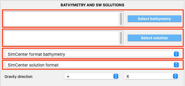
Fig. 2.4.2.1.1 UI for loading bathymetry and shallow-water solution files
Note
Please provide as much of the bathymetry as possible. HydroUQ will crop the required areas for the CFD simulation.
The solution files can be large in size. Hence, it is recommended to restrict the times required for the CFD simulation only. Here, it is essential to note that the boundaries can lead to unphysical accumulation if there are excessive reflections.
Bathymetry
Here the user needs to select the bathymetry files of the ocean floor. At present, HydroUQ can directly read the bathymetry provided in the GeoClaw format (Type 1) or the SimCenter format. For more information about the GeoClaw file format, check out Topography. Similarly, for the SimCenter formats, check out Topography: SimCenter.
The other input is the direction of gravity. For this type of simulation, it is recommended to use -z for the gravity direction.
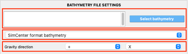
Fig. 2.4.2.1.2 UI for loading bathymetry of the ocean floor
Note
The entire bathymetry provided is considered for the CFD simulation. Hence, please be mindful of the model size, especially if the bathymetry is very rough. A very irregular bathymetry can require refined meshes leading to longer computational times.
STL file
Here the user needs to provide the STL files related to the geometry here of the ocean floor. In addition, it is required to provide separate STL files for all the boundaries and buildings. The files need to be in the ‘STL ASCII format. The files need to be named as
Entry.stl - This is the patch for the inlet of the fluid
Exit.stl - This is the patch for the outlet of the fluid
Right.stl - This is generally a wall patch on the right. Here, if one were to stand at the inlet and face the outlet, this is the wall on the right.
Left.stl - This is generally a wall patch on the left. Here, if one were to stand at the inlet and face the outlet, this is the wall on the left.
Bottom.stl - This is the ocean floor or the flume bathymetry
Top.stl - This is generally a surface high enough such that the air velocity does not affect the wind-water interface
Buildings.stl - This is the building of interest on which we aim to determine the structural response
Otherbuildings.stl - These are the other buildings around the structure of interest and could affect the flow around the structure of interest.
The other input is the direction of gravity. For this type of simulation, it is recommended to use -z for the gravity direction.
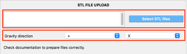
Fig. 2.4.2.1.3 UI for loading the geometry as STL files
Note
It is necessary to provide each of these
STLfiles separately. Hydro-UQ uses them to determine the boundary conditions accurately.
Wave flume
This constitutes the geometric definition of the wave flume. This is the first step in the description of the digital twin for the wave flume. One of the inputs is the direction of gravity. For this type of simulation, it is recommended to use -z for the gravity direction.
Standard OSU flume
The flume geometry can be defined using the standard flume definition. Here, a common flume geometry for the Large Wave Flume at the O.H. Hinsdale Wave Research Laboratory in Oregon State University. This is selected as shown in Flume02.
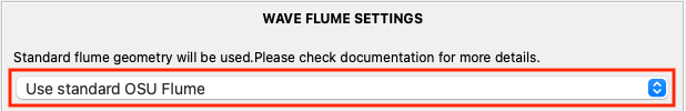
Fig. 2.4.2.1.4 Using the standard wave flume geometry
The geometry of the wave flume is defined by providing the coordinates of the external profile of the wave flume, as shown below.
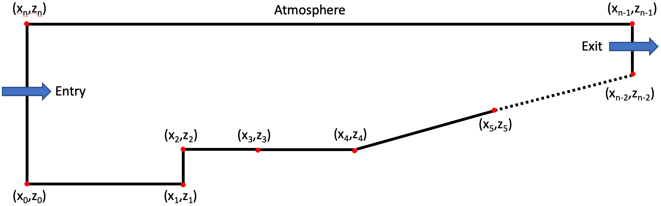
Fig. 2.4.2.1.5 The coordinates representing the external profile of the wave flume
The coordinates of the standard wave flume are provided below.
-2.085,0
14.2748,0
14.2748,0.1524
17.9324,0.1524
28.9052,1.15
43.5356,1.7526
80.116,1.7526
80.116,4.572
-2.085,4.572
Definition by coordinates
Alternatively, the user can define their own custom wave-flume geometry, as shown below. Here, the user needs to specify the x (along the length) and z (along the height) coordinates in a tabular format. Additionally, breadth also needs to be provided to define the wave flume geometry uniquely. This is similar to the geometry defined above for the standard OSU flume. HydroUQ constructs the STL files necessary for the CFD simulation process using the provided coordinates and the breadth.
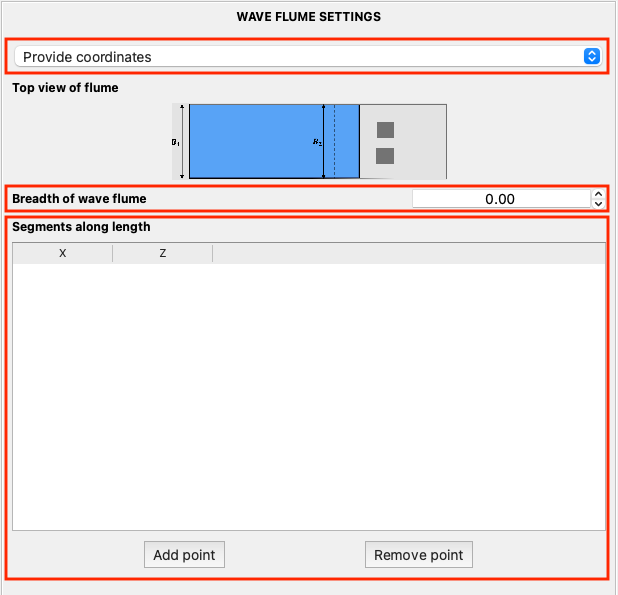
Fig. 2.4.2.1.6 Defining a custom wave-flume geometry
Note
The breadth of the flume needs to be greater than 0. If the breadth is too small, this can lead to numerical issues.
2.4.2.2. SW-CFD interface
The shallow-water to CFD interface can only be defined for the simulation type where CFD is used to resolve the shallow-water solutions. The interface is specified using a .csv file and uploaded as shown in Fig. 2.4.2.2.1.
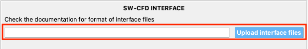
Fig. 2.4.2.2.1 Uploading the .csv file that defines the interface
Consider the problem description as shown in the Fig. 2.4.2.2.2. Consider an event (earthquake on a fault or low-pressure due to a hurricane) represented by the red line on the left. The shallow-water solvers are used over the Ocean domain. In order to provide a high-fidelity solution for the structural response, the shallow-water domain is further refined using 3D CFD. The yellow boxes represent the shallow water to CFD interfaces. This interface information is provided in a .csv file.
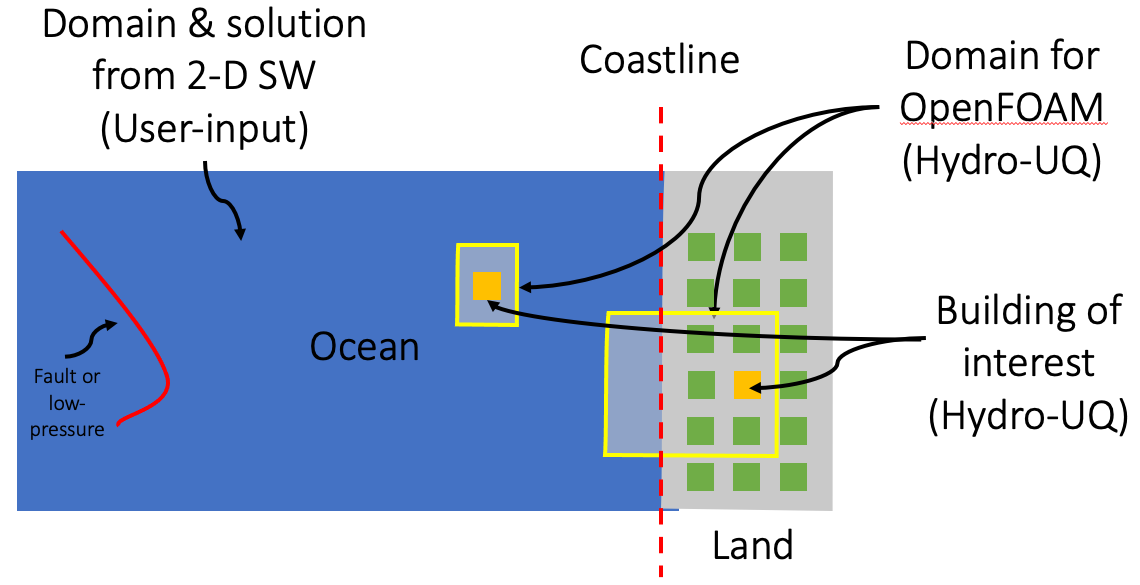
Fig. 2.4.2.2.2 Visual depiction of the shallow water to CFD interface
A typical interface file is shown below.
Entry 0 0 0 1
Exit 1 0 1 1
Right 0 0 1 0
Left 0 1 1 1
The .csv needs four patches to be explicitly defined. The first is the patch name, followed by the x and y coordinates of the first and second points. The order of the points or the patches do not matter. The physical meaning of the patch names are as given below:
Entry - This is the patch for the inlet of the fluid from the shallow water to the CFD domain.
Exit - This is the patch for the fluid outlet from the CFD domain.
Right - This is generally a patch on the right. Here, if one were to stand at the inlet and face the outlet, this is the boundary on the right.
Left - This is generally a patch on the left. Here, if one were to stand at the inlet and face the outlet, this is the boundary on the left.
Note
It is necessary that the point provided to define the interface needs to be closed and a quadrilateral.
The patch names need to be provided to identify appropriate boundaries.
2.4.2.3. Buildings/specimens
Buildings or specimens can be defined in the EVT. It is important here to note that there can be two types of buildings: (a) Building of interest for which the structural response is measured (b) Other neighboring buildings that impact the flow fields.
These can either be defined manually in a tabular format or parametrically as shown in Fig. 2.4.2.3.1.
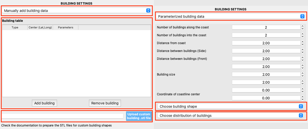
Fig. 2.4.2.3.1 Building definition in the EVT
For the manual definition of the building, a tabular format is used for the user to specify:
Building type (type): This refers to the shape and type of building. An index is used to identify the type of building:
-2: This is the building on which the structural response is required. The building definition is as provided in the
GIwidget tab earlier. Here the building shape is generally cuboid.-1: This is the building on which the structural response is required. However, this is provided in the
SIMtab as an OpenSees script for complicated building shapes. For this type of building, please also upload theSTLfile, in ASCII format, for the building shape. This is required to accurately capture the flow fields around the building.1: This is a building on which structural response is not desired. However, this is present in the neighborhood and can significantly affect the flow fields. The shape of the building is cuboid here.
2: This is a building on which structural response is not desired. However, this is present in the neighborhood and can significantly affect the flow fields. The shape of the building is more complex and provided through an
STLfile in ASCII format.
Note
At present, HydroUQ only supports one type of building to be defined using a
STLgeometry. This file needs to be in ASCII format. This limitation will be removed in the upcoming versions.Center: This refers to the location of the building/specimen. This is defined in terms of the coordinates (
x,y,z) or latitude-longitude depending on the type of simulation chosen earlier in Project settings. Suppose the simulation is based on shallow-water to CFD or bathymetry settings. In that case, the latitude and longitude need to be specified. Else, the position is input in terms of the coordinates.Note
Here, the building position refers to the center of the bottom surface of the building. Thus, one needs to appropriately calculate the position of the building.
Parameters: This refers to the building’s length, breadth, and height definition. This is required only for building types 1. The parameters for the other types will be extracted either from the
STLfiles or theGIwidget tab.
The parametric definition of the building is recommended for usage mainly for the flume. This is recommended for usage when all the buildings are of the same shape and size. Here, the buildings are automatically generated based on a set of parametric inputs. The building of interest is directly determined by the HydroUQ app by using the coordinate information from the GI tab and matching it with the nearest building. The set of parameters include:
Number of buildings along the coast: This refers to the number of building in the direction orthogonal to the flow, i.e., between right and left interfaces or walls of the CFD domain.
Number of buildings into the coast: This refers to the number of buildings in the flow direction, i.e., between entry and exit of the CFD domain.
Distance from coast: This refers to the distance of the first building from (0,0).
Distance between buildings (Side): This refers to the center-to-center distance between the buildings in the direction orthogonal to the flow.
Distance between buildings (Front): This refers to the center-to-center distance between the buildings in the flow direction.
Building size: Here, it is required to specify the building’s length - breadth - height. This information can be the size of the building (for those with a cuboidal shape). Alternatively, this is the box into which an irregular building can be fitted.
Coordinate of coastline center: This refers to the center of the coastline from the global (0,0) of the domain.
Building shape: Here, two-building shapes are possible, i.e., cuboid or user-defined as shown in Fig. 2.4.2.3.2. If the building shape is user-defined, then an
STLfile in ASCII format needs to be uploaded.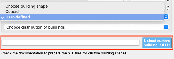
Fig. 2.4.2.3.2 Building shape definition in the
EVT¶Distribution of buildings: This refers to the distribution of the buildings. At present, this can be simple or staggered, as shown in Fig. 2.4.2.3.3.
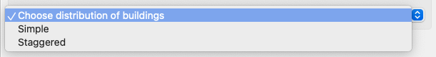
Fig. 2.4.2.3.3 Building distribution definition in the
EVT
2.4.2.4. Floating bodies
The present version of the HydroUQ does not facilitate floating bodies. These would be added to the upcoming versions of HydroUQ app.