2.4.1. Workflow Structure
The backend applications for the R2D app follow a standard workflow:
Read the configuration file. At the start of the workflow, the settings specified in the configuration file are parsed (Inputs). Note that if a particular component application is not included in the configuration file, it is automatically skipped in the workflow.
Pre-process building and event data. The workflow completes a one-time step of setting up BIM files (Building Application) for each building asset and assigning events to each building site (RegionalMapping Application).
Set up and run simulations for each building asset. From here, the workflow begins its iterative processes of running simulations for each building asset. The workflow runs two passes for each building asset: the supporting simulation files (from the Event, Modeling, EDP, and Simulation Applications) are set up in the first pass, and the workflow commands are executed in the second pass. At the end of the iteration, simulation results are used to perform damage/loss assessment (DL Application). When run remotely on DesignSafe, this iterative process is parallelized across computing resources.
Aggregate outputs for all building assets. After iterating through simulations, the workflow aggregates the content of individual EDP.csv, DM.csv, and DV.csv results for every building asset into single output summary files (Outputs).
The structure of a general workflow is depicted in Fig. 2.4.1.1 with the following keys:
User-provided input files are shown in orange.
Component applications are shown in blue. File dependencies for each component application are shown with arrows.
Intermediate files produced by the workflow to propagate data are shown in grey.
Output files provided to the user are shown in green.
Within the parallelized workflow for running each building asset simulation, two passes through the component applications are illustrated: the first pass in setting up the intermediate files (in red), then the second pass of executing the simulation and producing output results (in green).
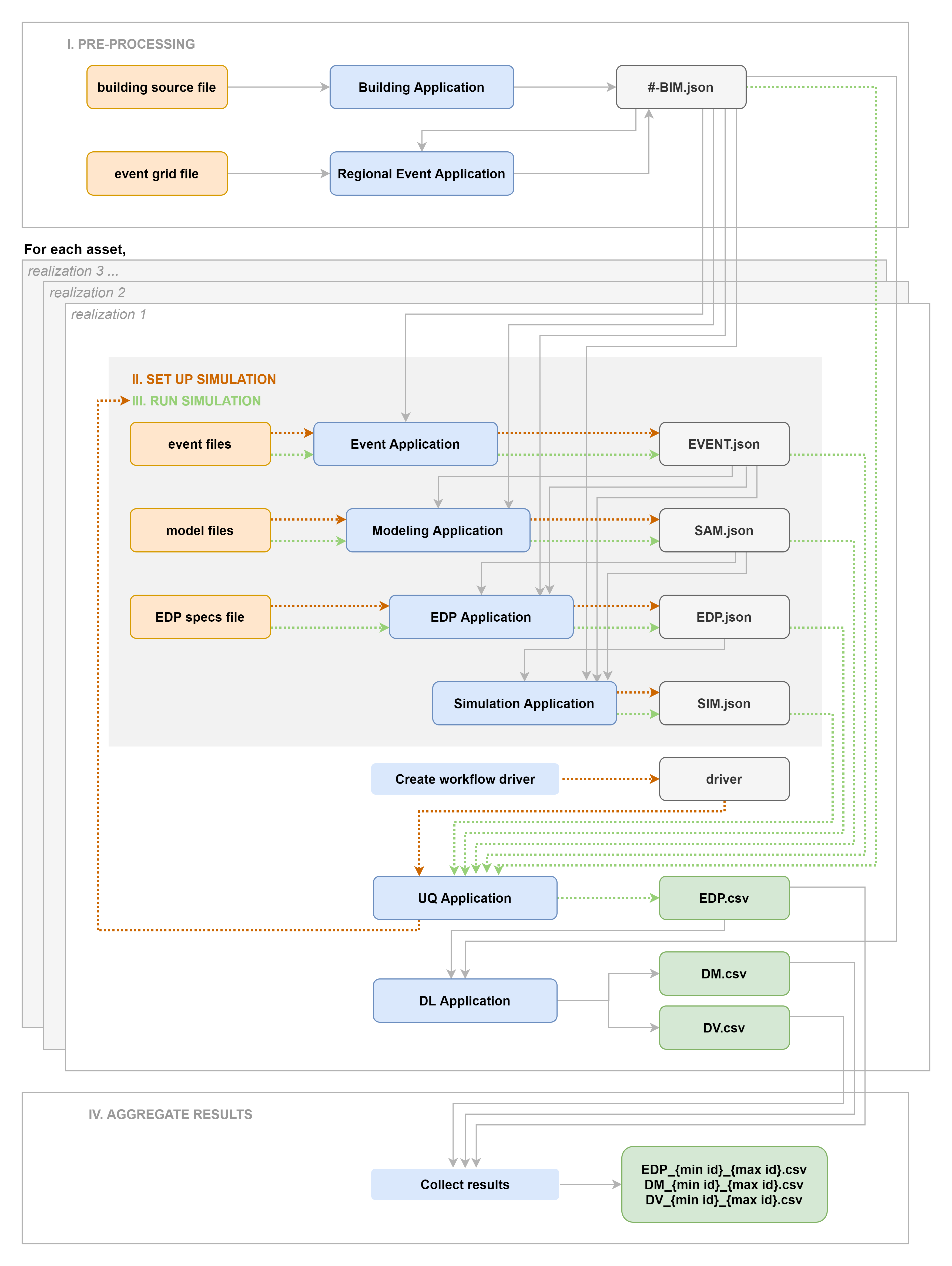
Fig. 2.4.1.1 Diagram of backend applications workflow.
To view the commands associated with each step of the workflow, refer to Reading the Log.