3.2. FEM: Finite Element Method
The FEM tab will present users with a selection of FEM applications. Currently, there are six options:
OpenSees
Python
FEAPpv
SurrogateGP (using a surrogate model trained in quoFEM in place of a numerical simulation model)
Custom (user-specified application)
Multi Model (using more than one model in an analysis), along with the option of specifying no simulation model.
The user must select one of these applications to proceed with the analysis. The user must also provide the necessary input files for the selected application. The input files required for each application are described in the following sections.
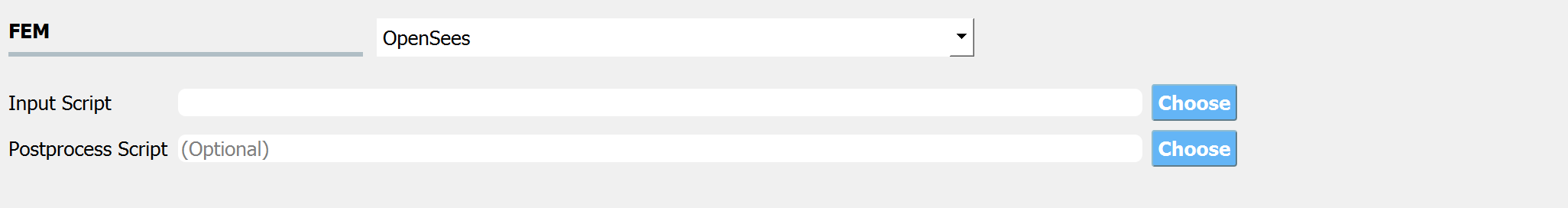
Fig. 3.2.1 Input for the FEM tab.
Note
Because the UQ engines treat the FEM applications as a black box, when the UQ engine runs each deterministic simulation it expects the FEM application to output a single file. This file must be named results.out and be placed in the same directory as the main input file. The results.out file must contain a single line. That line must contain as many QoI values as the sum of the length of all the EDPs defined by the user in the QoI panel. Each value must be separated by a space. An example results.out file for a problem specifying four response QoI values is as shown:
63.8314 43.312 0.846004 0.00587503
3.2.1. OpenSees
When the choice of FEM application is OpenSees (the default application), the user is presented with the input panel shown in the figure above and there are two entry fields for filenames:
Input Script: The user must specify a main input script. When entered the application will parse this file looking for variables set with the
psetoption (a unique set command to the OpenSees interpreter that is used to identify parameter values). For each variable whose value is set withpset, the program will auto-populate the variable in the RV tab.
# units kN & mm

#
# set some parameters
#

pset E 205
pset P 25
pset Au 500
pset Ao 250

#
# build the model
#

model Basic -ndm 2 -ndf 2

node 1     0    0
node 2  4000    0
node 3  8000    0
node 4 12000    0
node 5  4000 4000
node 6  8000 4000

fix 1 1 1
fix 4 0 1

uniaxialMaterial Elastic 1 $E

element truss 1 1 2 $Ao 1
element truss 2 2 3 $Ao 1
element truss 3 3 4 $Ao 1
element truss 4 1 5 $Au 1
element truss 5 5 6 $Au 1
element truss 6 6 4 $Au 1
element truss 7 2 5 $Ao 1
element truss 8 3 6 $Ao 1
element truss 9 5 3 $Ao 1
timeSeries Linear 1
pattern Plain 1 1 {
    load 2 0 [expr -$P]
    load 3 0 [expr -$P]
}

#
# create a recorder
#

recorder Node -file node.out -scientific -precision 10 -node 1 2 3 4 5 6 -dof 1 2 disp

#
# build and perform the analysis
#

algorithm Linear
integrator LoadControl 1.0
system ProfileSPD
numberer RCM
constraints Plain
analysis Static
analyze 1

#
# remove the recorders
#

remove recorders
Postprocess Script (optional): This is an optional entry where the user has the option of specifying either a tcl script or a Python script that will be used to post-process the results and create a
results.outfile after the main script runs. See for instance, example 1.
Note
The postprocess file can be either a tcl script or a Python script and the file extensions must be either .py or .tcl.
Warning
If a tcl script file is used and the user is reading results from files created with OpenSees recorder commands, the user must ensure there is a wipe recorders command at either the end of the main script or the start of the postprocessing script.
3.2.2. Python
The user provides a main script and has the option to provide 2 other scripts:
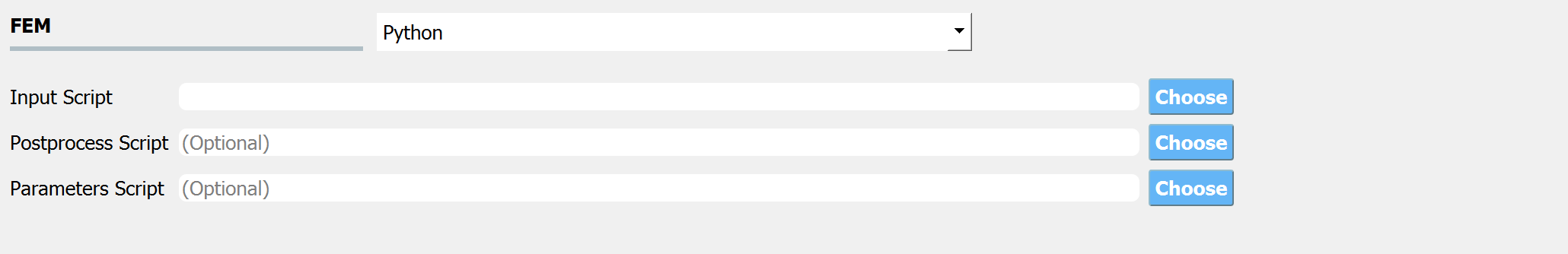
Postprocess Script (Optional): This must be a Python script which is provided the QoI variable names when started. This entry can be left blank if the main script creates a
results.outfile with a single line as described for the OpenSees application.Parameters File: This file allows for the automatic population of the RV tab with any variables found in the file. For example, if the file contained the following:
# set some parameters

E = 205
P = 25
Ao = 250
Au = 500
The RV tab would be populated with the
E,P,Ao, andAurandom variables. See example 2 for more. For users on Windows systems, see the important warning below:
Caution
Python on Windows. On Windows, quoFEM is bundled with its own python.exe, with the essential packages (including numpy, scipy, openseespy) already installed. By default, this python.exe is used to (1) run SimCenter workflow; and (2) run the user-provided python model. Therefore, please make sure to test your model using the “correct” python.exe before running in quoFEM.

Fig. 3.2.2.1 Windows Default Python Path found in File-Preference
“Pip install” Python packages
If your model requires additional Python packages, use the following command to install them.
{$PythonExePath} -m pip install {$PackageName}
where
{$PythonExePath}is the (default) python path shown in the preference window and{$PackageName}is the name of the python package.Use custom Python

Fig. 3.2.2.2 Custom Python Path
If you would like to use another version of Python in quoFEM, use the custom option in
File-Preference, then you will need to manually install the packages required to run the SimCenter workflow using the following command:{$NewPythonExePath} -m pip install nheri_simcenter --upgrade
where
{$NewPythonExePath}is the new python path specified in the preference window.
3.2.3. FEAPpv
FEAPpv is another FEM engine used by the quoFEM app that is publicly available from the FEAPpv page. FEAPpv is a general-purpose finite element analysis program that is designed for research and educational use. To install FEAPpv you must download the source code and follow the build instructions on the Source Code Download and Compile Instructions section of the FEAPpv page.
Similar to the OpenSees application, when the user selects FEAPpv the user is requested to provide two files.
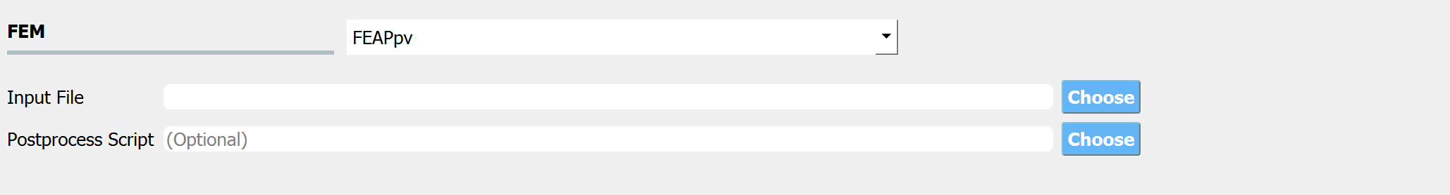
Input File: The user must specify a main input file. A part of this file may contain variables set in the
PARAsection. The variables in this section will be read by the UI when the file is entered and will be autopopulated in the RV tab. For example, if a file containing the following code was specified:
Postprocess Script: The user must provide the name of the Python script that will run when FEAPpv has finished executing. This Python script must load the output file from FEAPpv and create the
results.outfile. Currently, the user has no control over the name of the output file created by FEAPpv,SimCenterOut.txt. It is this file the post-process script must open and use, to create theresults.outfile.
3.2.4. Custom
This option allows users to specify custom simulation applications which do not
necessarily need to be limited to only Finite Element Method software. With this
option all users need to do is provide a driver script that takes the input file
generated by the UQ engine, parses and passes the inputs to the custom analysis
engine, and processes the results to meet the format requirements specified for
results.out. The inputs generated by the UQ engine will be provided in a
file named params.in and will always follow the format shown in the example
params.in file below. The first line specifies the
number of random variables while the subsequent lines first contain the name of
the random variable and the value of the current realization separated by a
space.
2
randomVariable 2.719191180014362e+02
anotherRandomVariable 7.518852020241320e+01
For the custom simulation application, the user provides at least two inputs:
The script that drives the simulations, which must be named
driver.baton Windows anddriveron MacOS and LinuxThe script that post-processes the simulation results and writes them to
results.outin the required format
Additionally, users can specify as many additional files and binaries as required by the application by increasing the number of input slots, as shown in Fig. 3.2.4.1. By specifying these files here, they will be copied to the correct location for quoFEM to access them during analyses. Users also have the option to simply place all the required files in the same location as the provided workflow driver script – quoFEM will automatically copy any files in this directory. This is particularly helpful if several applications with numerous inputs are all being called by the workflow driver script and avoids the need to explicitly input each one of these files.
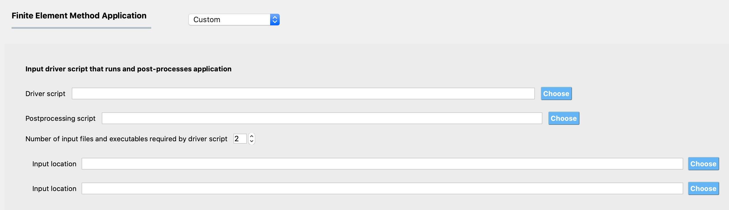
Fig. 3.2.4.1 Input for Custom Analysis Application
3.2.5. SurrogateGP
In place of the physical simulation models, the Gaussian process surrogate model trained in quoFEM can be imported for UQ/Optimization analyses.
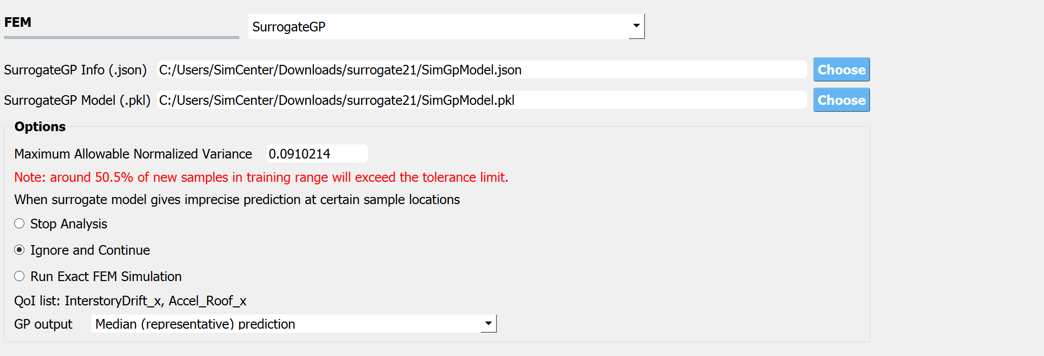
Fig. 3.2.5.1 Input for Surrogate model FEM Application
When users select the SurrogateGP option, they are requested to provide Surrogate info file (.json) that contains the information about the surrogate model. Users can open it with a text editor to see the contents. Once the file is loaded, users may choose the tolerance level of the predictive variance.
Maximum Allowable Normalized Variance: Prediction variance divided by the variance level of the training dataset. If more than one QoI is introduced, only the highest normalized variance value will be considered.
Warning
It is important to understand that the predictive variance does not necessarily imply the error level of the model.
The provided percentage ratio of the out-of-tolerance samples is only a rough guideline since it assumes that the samples are uniformly populated throughout the range the user provided during the training session. Therefore, if the user selects other distribution types and ranges, the percentage estimation will not be correct anymore.
Users may either stop the analysis, continue, or run exact FEM simulations whenever the tolerance limit is exceeded.
Stop Analysis: The analysis is immediately terminated. quoFEM will show the error (e.g. dakota engine gives “No dakotaTab.out file” error)
Continue: The tolerance level is ignored, and the analysis is continued. This option is not recommended.
Run Exact FEM Simulation: The program will run the exact FEM simulation user provided in the training session. In case the surrogate model is constructed purely based on the data and without any model information (case 3 in section 2.1.2.2), this option will be disabled. To allow this option, an additional folder that contains the simulation information is required. This folder, called Simulation template folder (templatedir_SIM), contains the simulator scripts (workflow driver) and required files to run the original simulation model. This file can be obtained by
Note
The surrogate model file (.json) and Simulation template folder (templatedir_SIM) can be generated from the quoFEM. See Gaussian Process (GP) Surrogate Modeling.
Additionally, GP output can be set as either the median prediction or a random sample generated from the normal distribution (or lognormal distribution if the user used log-transform when training) with the predictive median and variance. NOTE: that the random generator does not account for the Gaussian process correlation, and each realization of QoI given RVs is independent of each other. Only users familiar with GP modeling and who understand the limitations are recommended to use the random sample option.
If the user wants to inspect the simulation status or check error/warning messages related to the surrogate model, they can refer to the messages written at: {Local Jobs Directory}/tmp.SimCenter/surrogateLog.err. (Note: {Local Jobs Directory} is specified from the ‘File’ → ‘Preferences’ in the menu bar.)
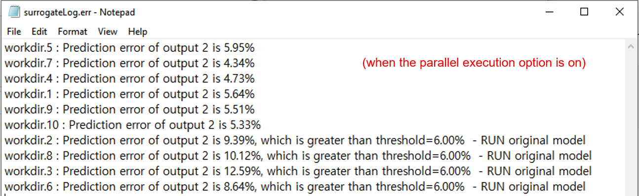
Fig. 3.2.5.2 Example of surrogateLog.err file
Note
Once the surrogate model is imported, the RV and QoI tab will be auto-populated. Users are allowed to remove some QoIs if not interested but may not add new QoIs or modify the names of existing QoIs.
3.2.6. Multi Model
By selecting this option, users can define multiple numerical simulation models for use in their UQ analysis. The Add and Remove buttons allow users to control the number of models they want to use in the analysis.
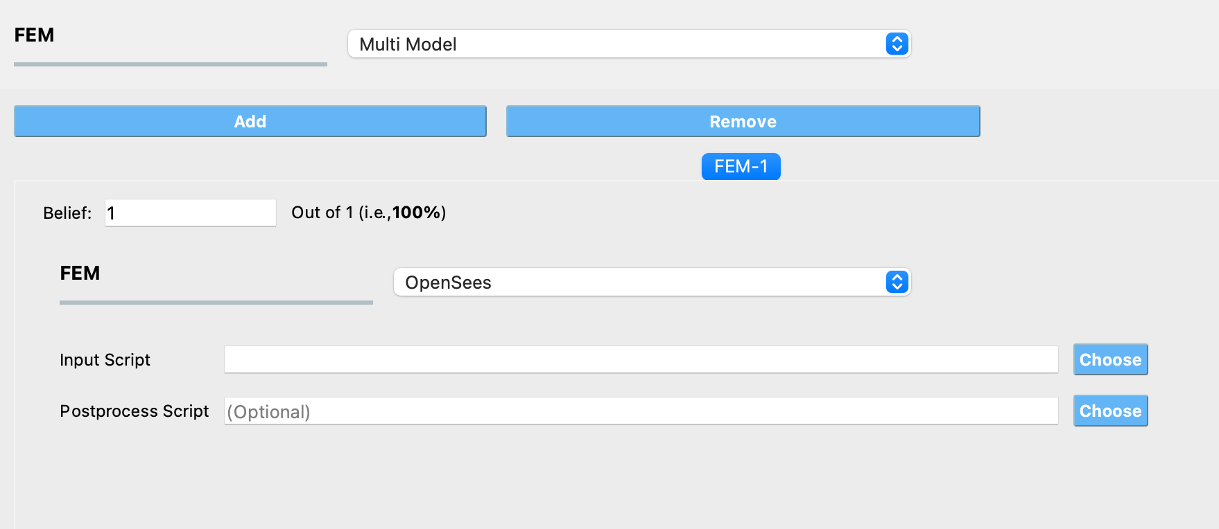
Fig. 3.2.6.1 Input for Multi Model FEM Application
By adding a model, a new tab is created in the FEM panel where users can choose one of the FEM applications described in the sections above and provide the inputs necessary to define the model. Users also need to specify their belief about the credibility of the model in the tab corresponding to that model. The beliefs are expressed as non-negative numerical values. The belief value for each model is defined relative to the other models, and the beliefs do not need to sum to 1.
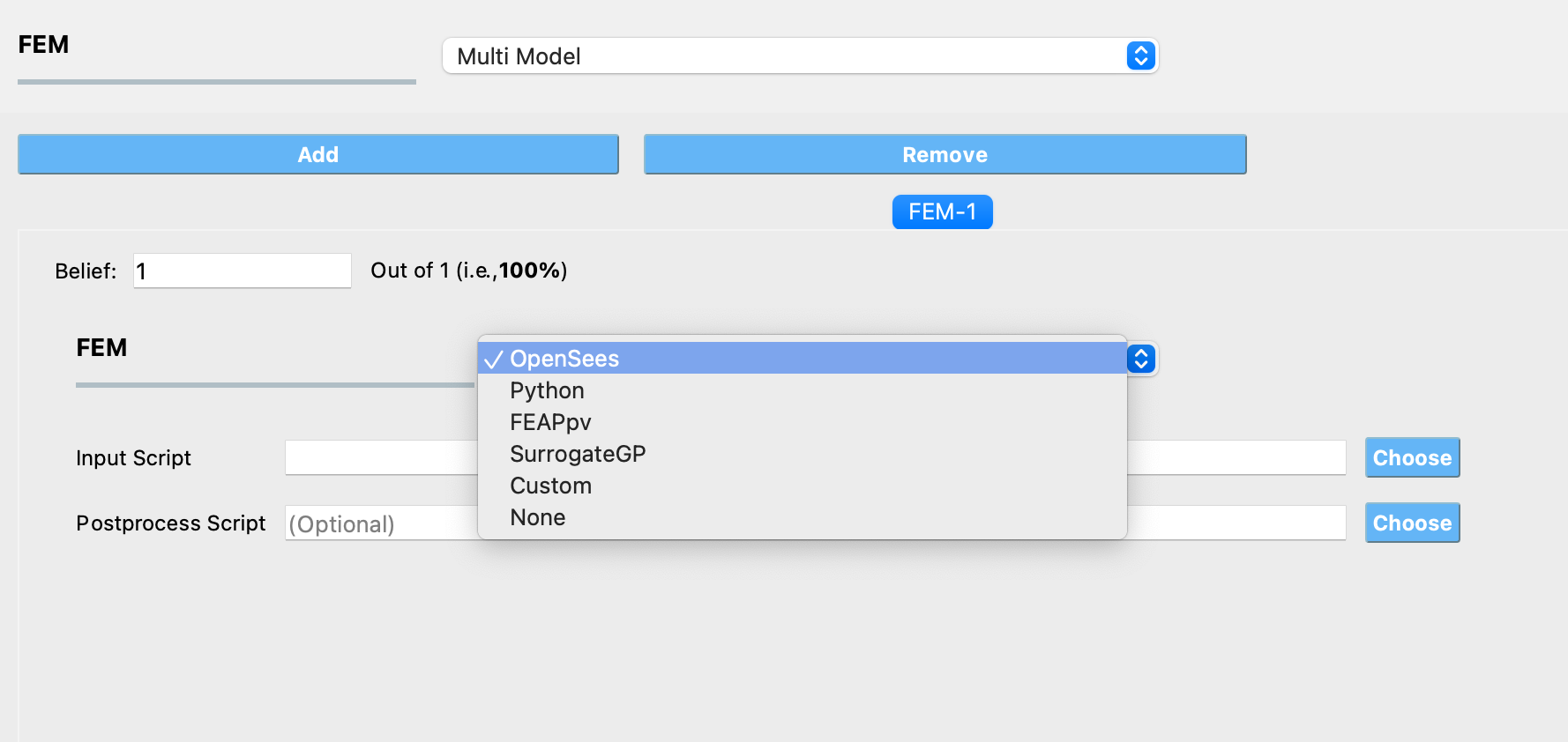
Fig. 3.2.6.2 Selecting a FEM application within a model tab
Note
If a Multi Model application is selected, at least 2 models must be defined.